
S13 Digital Climate Control Guide
The Final S13 Digital Climate Control Guide you’ll ever need.
Why this guide was made.
I could not have made this S13 Digital Climate Control Guide without the help of those who have come before me. I want to give a special shout out to NismoLK and KoukiMonster on NicoClub who really helped me find my way through. So at the end of the day I’m maybe contributing like 15% new information.
The whole reason I ended up making this s13 Digital Climate Control Guide, is that during my installation, I found a few things on the guides to be incorrect, not accurate, or simply out of date. A good example is that the clips and rod suggested by NismoLK, did not fit correctly, and weren’t holding. I’ve also created a wiring diagram that limits the amount of wires you have to splice into, to one single wire.
Also, with Zilvia having finally met its end, its only a matter of time before forums get lost completely. Or people get tired of ads, or pictures no longer showing up. So I wanted to create something that I had some control over, and hopefully help give back to the 240sx community in a small way. I hope this helps all 2 of you who are crazy enough to do this mod in the year of our lord 2026.
Please read the entire guide before making any purchases. Just so you know exactly what you need, or don’t need.
Tools Needed
- Drill
- Dremel
- Drill Bit
- Spade Bit
- Multimeter
- Phillips Screwdriver
- 10mm Socket and Ratchet
- Terminal Crimper
1. PARTS
S13 Digital Climate Control
Obviously you will need the Digital Climate Control itself. The best way to purchase is on E-bay. But they are getting kind of pricey. That being said, there are two versions for the S13, but there is really only one difference and that is the connector on the rear of the box. The Chuki (1991-95) has a ZEXEL part number ending in 52F00, and a Kouki (1996-98) has a ZEXEL part number ending in 60F01.
Just be sure you know which version you’re purchasing, as you will have to purchase the correct connectors. Everything else should be the same.
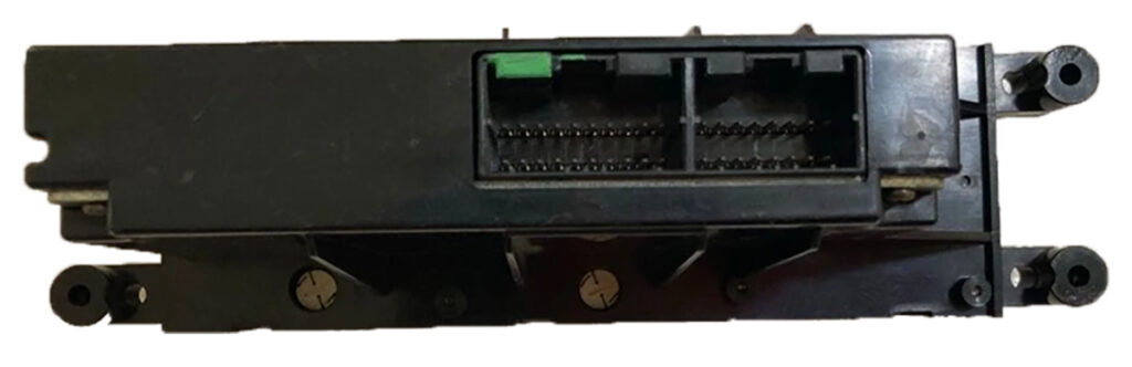
Chuki DCC Rear Connection (1991-1995)
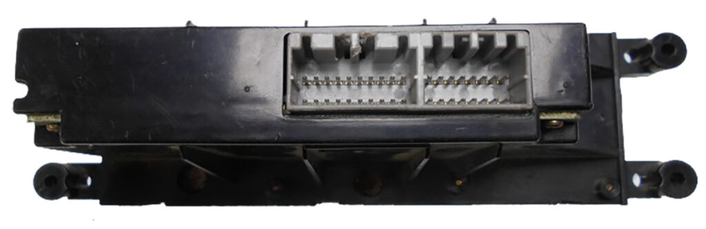
Kouki DCC Rear Connection (1996-1998)
Wiring Harness
Okay, so, elephant in the room. Making a harness seems like a huge pain in the ass, and it kind of is. You need specific crimping tools, you need all kinds of different connectors, relays, and pins. Then you need a wiring diagram, that takes a degree to actually understand. So I decided to try and simplify it, at least the diagram part. You’re still gonna have to be comfortable with crimping pins on connectors, and understanding basic wiring. But hey, you’re wanting to install a useless Climate Control Mod onto your 240sx you’ve clearly got that “special hyperfocus on 90’s JDM cars” kind of ’tism, so it won’t be an issue! I’ve also done all the research, and found the different connectors, and where to purchase them for relatively cheap. So at most its kind of like a bit of a LEGO adventure in wiring.
Electrical Connectors for the Harness
Connector | Part Number | Terminals | Link |
|---|---|---|---|
16-Pin Dash Interface^ | Yazaki 7122-7960 | 62 Connector C Type | Purchase |
16-Pin DCC (Chuki) | AMP MLC040-16s | Multilock 040 Socket | Purchase |
20-Pin DCC (Chuki) | AMP MLC040-20s | Multilock 040 Socket | Purchase |
16-Pin DCC (Kouki) | AMP MLC040MK2-16s | Multilock 040 Socket | Purchase |
20-Pin DCC (Kouki) | AMP MLC040MK2-20s | Multilock 040 Socket | Purchase |
Maxima Blend Door * | Yazaki 7123-7861-30 | 62 Connector C Type | Purchase |
Outside Ambient Sensor | Sumitomo RS. T1-2s-2 | RS-SKT | Purchase |
Cabin Air Sensor | Yazaki 7283-8629 | 91A-SKT1 | Purchase |
Acessory Connector (F) ** ^ | Yazaki 7123-1660 | Yazaki 7116-1230 | Purchase |
Acessory Connector (M) ** ^ | Yazaki 7122-1660 | Yazaki 7114-1230 | Purchase |
Sunload Sensor | Tyco 174056-2 | Multilock 040 Socket | Purchase |
4-Pin Relay Connector | NA
| 91MLC-SKT | Purchase
|
6-Pin Fan Control *** | NA | Various Spade | See 3D Print |
^ The vendor, Mouser, does not include Terminals with purchase of housing connectors. So make sure you purchase the Terminals separately. The connectors ordered from Corsa-Technic do come with sockets.
* So, this was a pain in the ass. No one sells these individually. The best I could find was a company that sells them in semi-bulk, at like 25 pieces a pop. Which is quite expensive. So while technically you can buy these new. I’d suggest just buying a Maxima Blend Door pigtail used, or getting one at a Junkyard. You could also just cut the pigtail of the Blend Door Motor if you’re getting one from a junkyard, and save quite a bit of money.
** In my wiring design, for ease of routing, I added a connector in place of an existing one on the JDM harness that isn’t used. This connector ties the Sunload Sensor, Cabin Temp Sensor, and Outside Cabin temp sensor wires into one plug. So you can route the long wires where they need to go, and just have a plug that you can clip into, so you don’t have to cut, or pull the whole harness if you need to take the harness out for any reason. You don’t need these ones specifically. Any 4-pin connector would do just fine!
*** I could not for the life of me find this connector. Thankfully its kind of a flat spade connector, so 3D printing a housing for it that works relatively well was simple enough. See the 3D printed parts section.
Sensors & Actuators
These are the Sensor and actuator parts you will need to purchase to make sure everything works correctly. These CAN all be purchased new, so you don’t have to try and hunt and wait to find them at a junkyard or on E-bay. Though some of them you probably should, because it will be cheaper.
Part Needed | From Where | Part Number | Link |
|---|---|---|---|
Blower Motor Resistor | 1996-99 Q45 | 27761-4BA0A | Purchase |
Blend Door Actuator * | 1996-99 Maxima | 27732-40U00 | Purchase |
Outside Temp Sensor | 1997-06 Q45 | 27710-31U00 | Purchase
|
Cabin Air Sensor ** | 2003-14 Murano | 27720-15U00 | Purchase |
Sunload Sensor | 2015-19 Murano | 27721-3AA0A | Purchase |
4-Pin Relay | Nissan | 25230-79981 | Purchase |
Blend Door Bracket | NA | 27156-51E00 | Purchase |
Rod | NA | NA | Purchase |
Rod Clips | NA | NA | Purchase |
* The Blend door Actuator is very specific. It has to come from a 96-99 Maxima. It kind of shares a part number with an Infiniti I30 of similar years. However the connector is different, as is the actuating arm. This is probably the most expensive piece of the whole project if you purchase it new at $250. You should try to see if you can source one from a junkyard, or a used on on E-Bay.
** Inside Cabin Air Temp Sensor is also a bit pricey New at $55. But you can get these very cheaply and very easily at a Junkyard or on E-Bay.
3D Printed Parts
Some of the parts Needed to do this conversion don’t exist elsewhere. So I had to get handy, and try to figure out how to 3D model. With mild success. Below is a list of the parts that I’ve created, to make everything work decently. I feel like 3D printing these parts is fine, as they aren’t super structural, nor will they see a ton of wear and tear.
As these parts are going to be in your car, in likely high temperatures, its best to try and print these with ASA, or ABS plastic. They are also modeled to have M4 Brass Threaded Inserts pressed in. However, you can probably get away with some bolts and nuts to secure most of it. I realize that this can add a bit of a complication, as not everyone has a 3D printer. But you can use online shops that will print things for you, and send them to you.
Lastly, I’m not a professional engineer. Some of these designs are likely going to be a bit wonky. Or may not be very well engineered. So if you can make it better, please do!
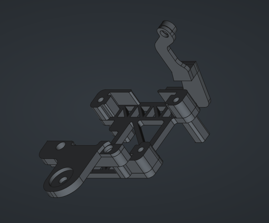
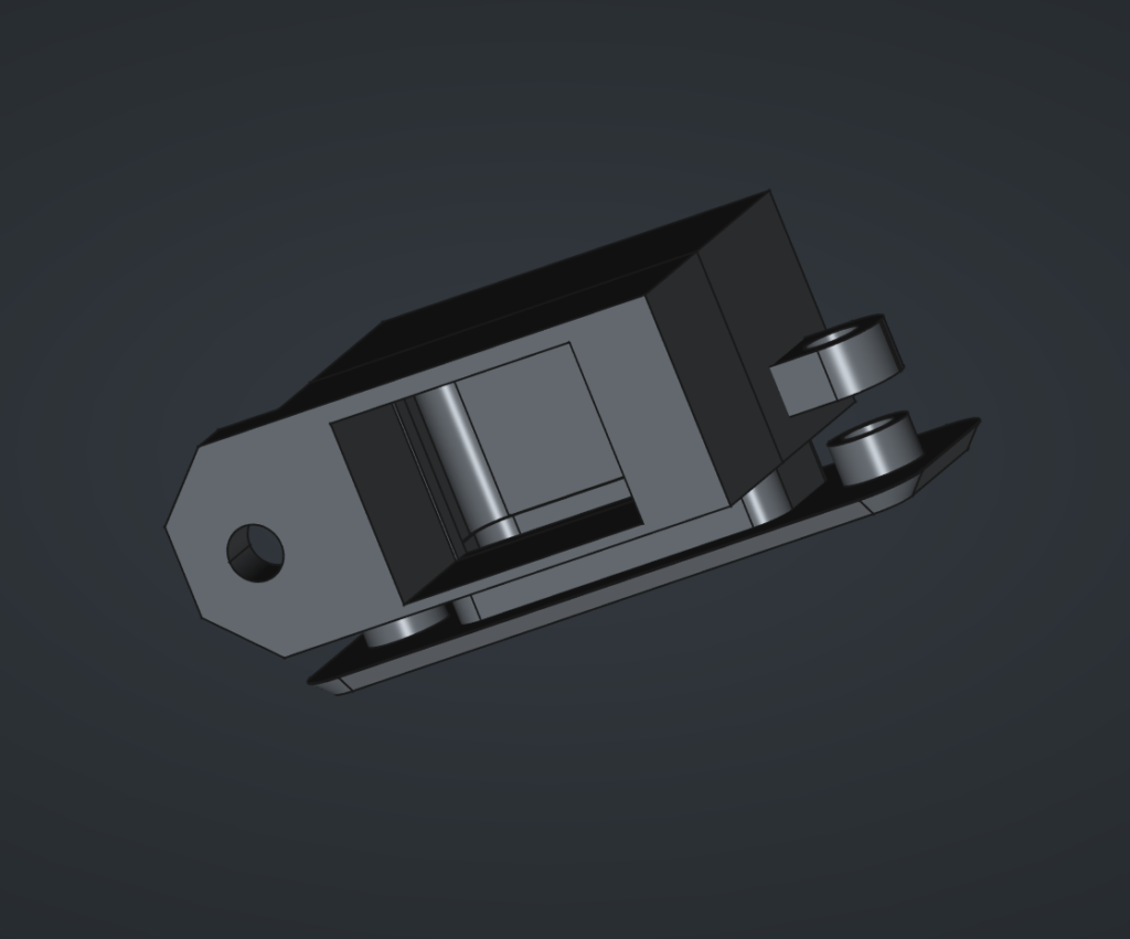
1. Maxima Blend Door Actuator Bracket
The Blend Door Motor needs to be placed in a position that doesn’t interfere with any other operations of the car. Also the Maxima Blend door is a bit bulky, and is difficult to place where the OEM one should go. So to solve this, I made a bracket that allows you to place it low in the center console cavity, and bolts in with a 10mm Flange Nut, and a Screw that goes into the HVAC box.
This 3D print has 4 parts to it. The Base Bracket itself. Stand off Legs of various sizes for your own needs. The front Bracket which goes onto the stud. And the rear Bracket which connects to the HVAC Box.
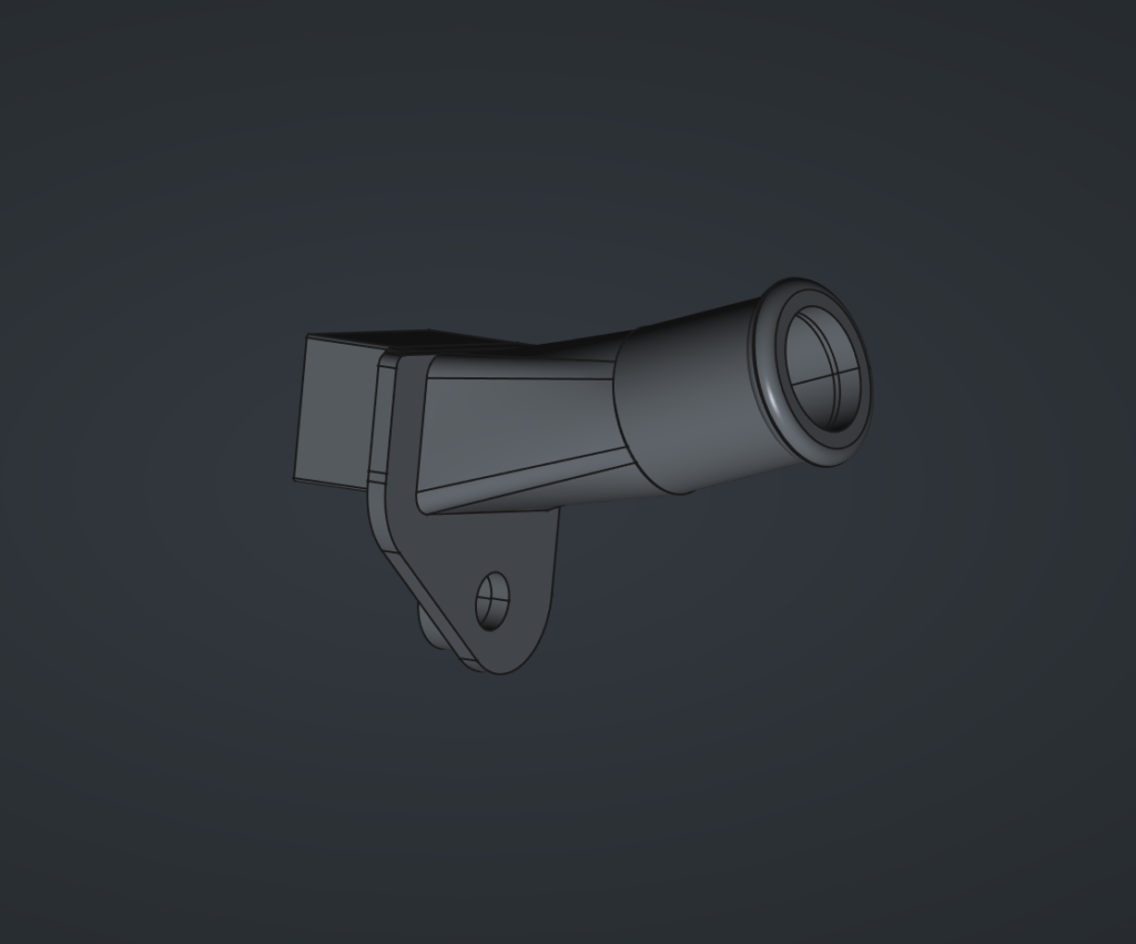
2. Aspirator & Accessories
The Ambient Air Temp Sensor needs to draw air in from the cabin, so that it can adjust the temperature to reach the desired setting. This however is difficult because the aspirator was made for RHD cars, and thus, the cut out is reversed, and it doesn’t fit. Beyond that this aspirator is meant to use the Venturi principle to create suction, and pulls air into the sensor, as opposed to pushing it out.
This aspirator Hose is just a single port that goes from the HVAC box, and moves the actual Venturi creating device further away where there is more room. And allows you to run a tube to the left side of the lower Dash cover above the drivers knees.
There are three aspects to this. The Aspirator connector which is shown. The Venturi Adapter (not shown). And the Venturi device itself (not shown), which is just copied from the mid 90’s Maxima/I30 Aspirator. Which means you can just get that part at a junk yard if you need it.
3. Ambient Air Temp Bracket and Grill
With all the parts above, you should now have suction coming from a hose. That hose needs to attach to the Ambient Air Temperature Sensor. But that sensor needs to pull in air from the cabin to get the correct measurement. Of course, our USDM cars do not have a place for this to actually go. So we have to create one.
The easiest, and most out of the way place that made sense to me, was on the Lower Dash Panel on the left side. So you have to cut out a rectangle and two holes to fit the grill. And then from behind the panel, attach the bracket to the grill, sandwhiching it. Then you can attach the sensor to the bracket, and connect the hoses, and you have a discreet, but functional Cabin Temp Sensor.
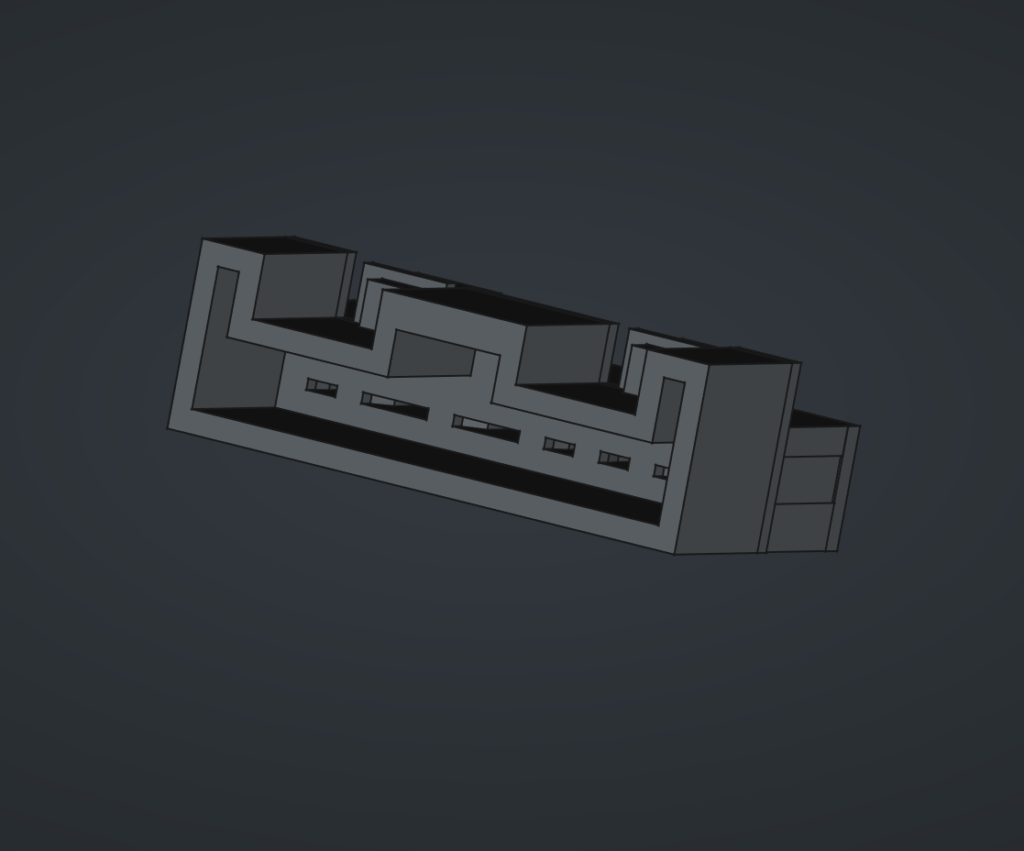
4. Fan controller electrical connector
I tried. I tried a lot to find this connector. And that is no small thing, considering I’ve spent hours upon hours searching online for connectors. This one does not exist. Even having contacted Corsa-Tech, to which they say they don’t know what it is. Alas, it cannot be found.
Fear not. For I, in my limited skills, have created a Connector in FreeCAD, that will work. It snaps in like an OEM plug. And should hold firmly enough. You will need to purchase Terminals, but you can get the correct ones on Amazon for like $10. Just crimp them to the wires. And insert them into the back, and fix the holder in place with some screws.
Wires
You’ll need wires to complete this job. They don’t have to be color coded to what is in the Diagram. But they should be rated for Automotive. So you want to get GXL, or TXL rated wires. I suggest getting 18AWG TXL wire for most of the wires. And like 2 feet of 14AWG TXL wire for the thicker fan connector wires. and 22AWG TXL wires for the sunload sensor and inside cabin air sensor. These were the three sizes that seemed to match up with the sizes of the original JDM harness.
A little bit of a lesson for you. In Japan they have AVSS which is a part of the Japanese Standard JASO D611. Where as in America, the Standard is based off of SAE J1128. They are both Thin walled wires, meant for automotive. A neat little rabbit hole I fell down. At the end of the day finding decent prices, and variety on AVSS wire was not easy, and its ultimately some copper strands in insulation, so TXL it is!
Miscellaneous
You’ll need a few other things to complete this install, that aren’t specific enough to have included in previous categories
- 2ft Tubing/Hose
- Super Glue/Rubber Beutal
- Wire Loom Tape (Tessa Tape)
- Your Mitts!
2. WIRING
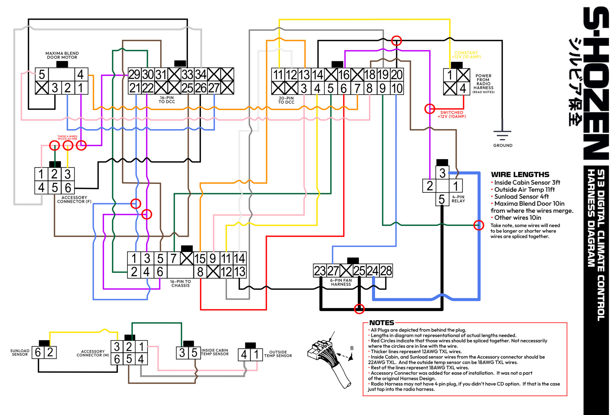
Wiring Diagram
Below is my attempt at a wiring diagram. I’m no engineer, or electrician. So bare with me. But I’ve adjusted the JDM harness so that it is as plug and play as possible. If your 240sx had the CD player option, you should have a 4-pin plug on the radio harness that you can plug into for +12v Constant, and +12v Ignition at 10amps. Which is what the FSM requires for those wires. The only wire that isn’t plugged in anywhere as of right now, is the Ground wire. Which can just be attached to the body. If you don’t have the 4-pin connecter, you will have to splice those wires into the radio harness wires, which should be Black/Red for constant, and Blue for Ignition.
Wire lengths should be around 10 inches in length. Save for the Ground Wire, +12v Ignition, and +12v Constant, which need to be longer to reach the Radio harness and ground comfortably. But, you can do pretty much whatever you want.
The exceptions here are the Cabin Air Temp sensor wires which should be 2.5 to 3 feet long. The connector to the Maxima Blend door should be 10 inches from the point all the sensor wires splice together.
And off the Accessory Connector, The outside Ambient Air Temp Sensor should be about 11 feet long, to reach the front of the car outside. And then the Sunload Sensor which goes to the vent at the top should be about 4ft long.
Notes
• All Plugs are depicted from behind the plug.
• Lengths in diagram not representational of actual lengths needed.
• Red Circles indicate that those wires should be spliced together. Not neccessarily where the circles are in line with the wire.
• Thicker lines represent 12AWG TXL wires.
• Wires to the Sunload Sensor, and Inside Cabin Air Temp Sensor should be 22AWG TXL wires. This is because the connectors are small, and need a thinner wire.
• Rest of the lines represent 18AWG TXL wires.
• Accessory Connector was added for ease of installation. It was not a part of the original Harness Design.
• Radio Harness may not have 4 pin plug, if you didn’t have CD option. If that is the case just tap into the radio harness.
3. DISASSEMBLY
General Rule of Thumb. Be cautious. A lot of this stuff is old 35 year old plastic. Be gentle and don’t pull too hard. You’ll need a 10mm Socket, and a Phillips Head Screwdriver to disassemble the interior of the car.
Tools Needed
- Phillips Screwdriver
- 10mm Socket and Ratchet
1. Gain access to the Climate Control Unit.
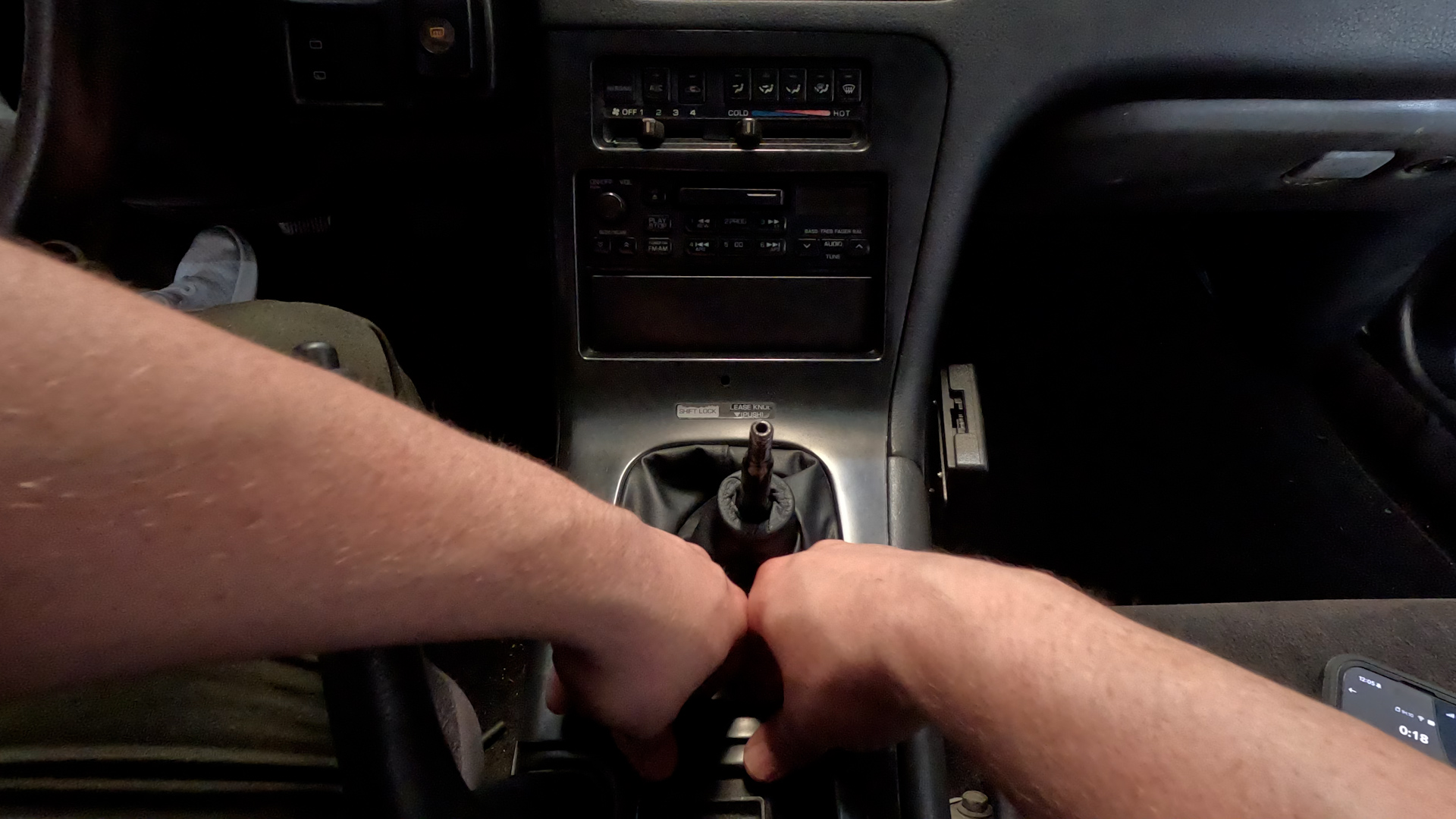
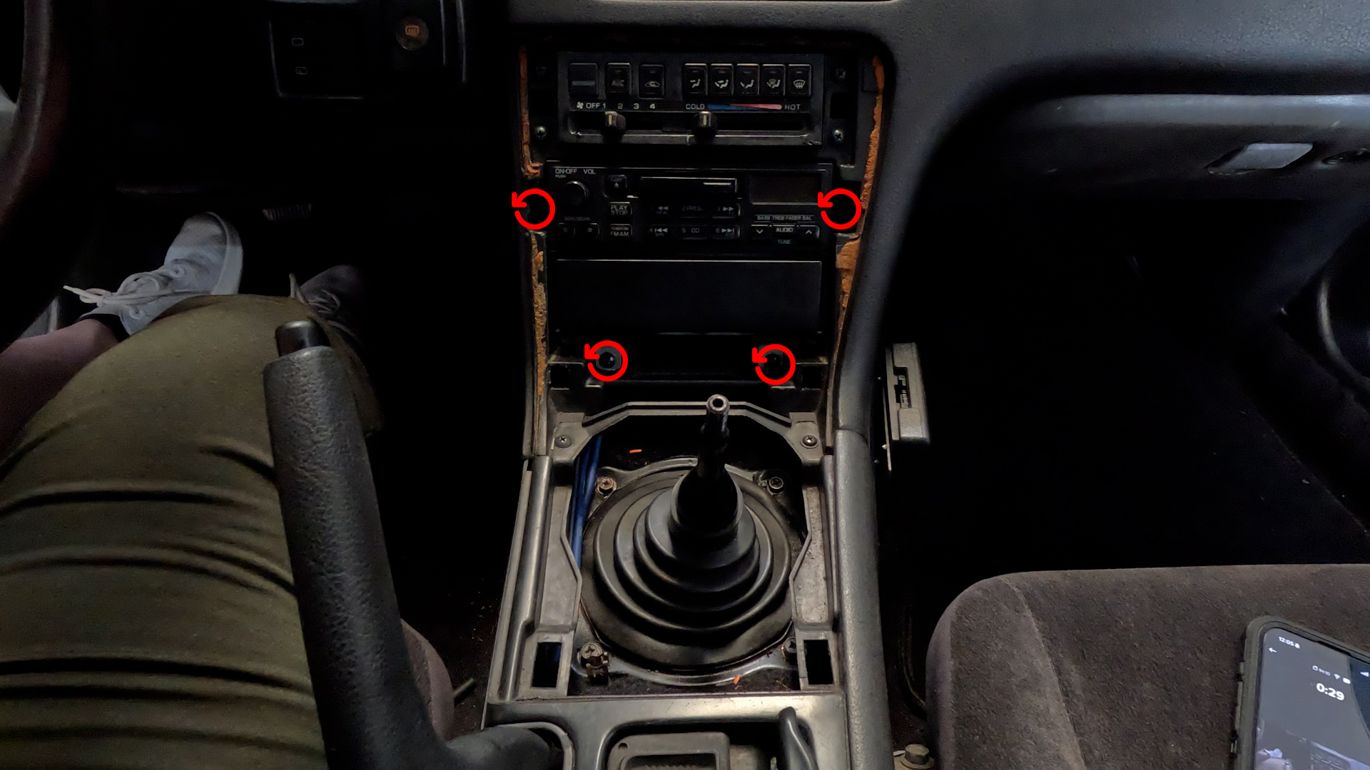

- Remove the Shift Knob by turning it Counter-Clockwise til it comes off.
- Remove Center Console Cover by reaching under the ring of the Shift Boot, and pull up. And gently work your way around til the piece is fully removed.
- Remove Radio Bracket with the 4 philips head screws. Pull radio out, and disconnect the wires and Antenna.
2. Remove Glove Box and frame.
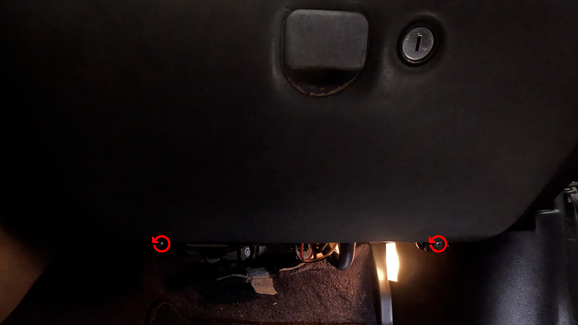
- Remove the Glove Box by removing the 2 philips head screws below the glove box. Then turn the box a bit to get the two studs to come out of the frame. Set aside.
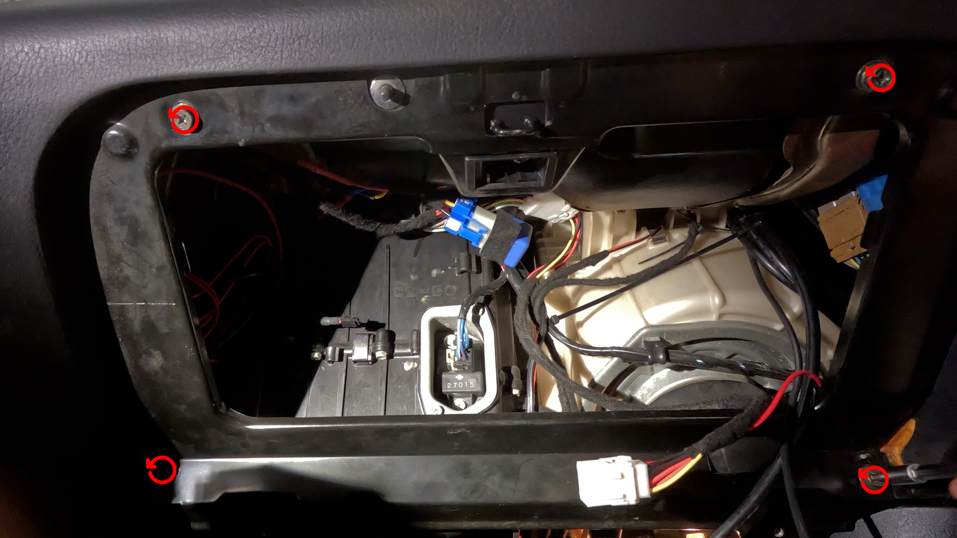
- Then remove the Mounting Plate for the Glovebox. Its four screws, and the plate should just pull out.
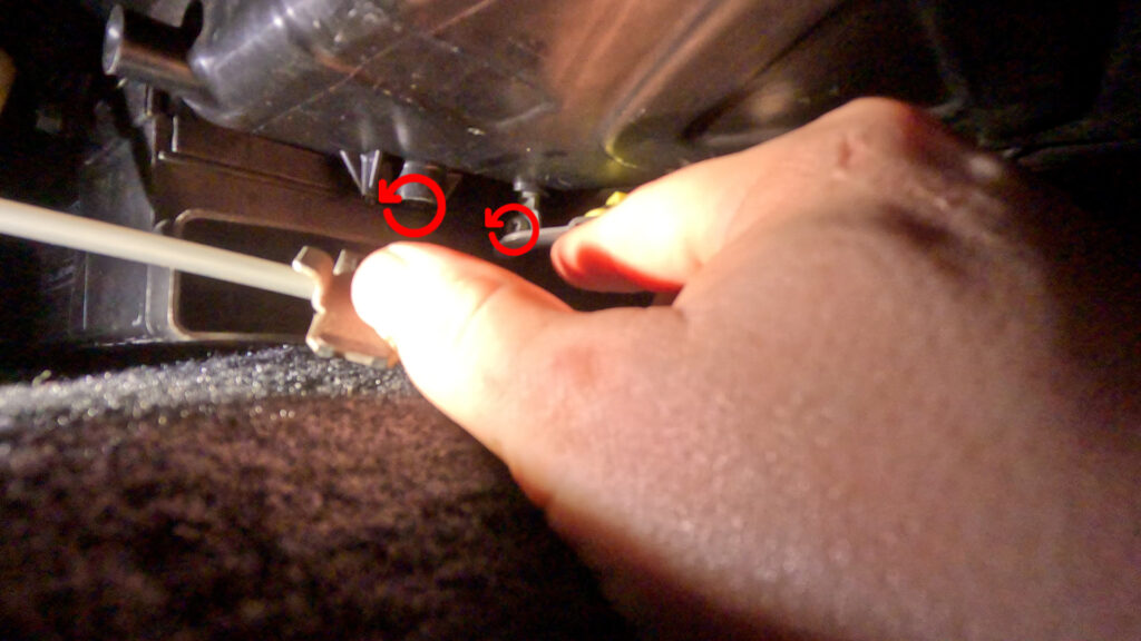
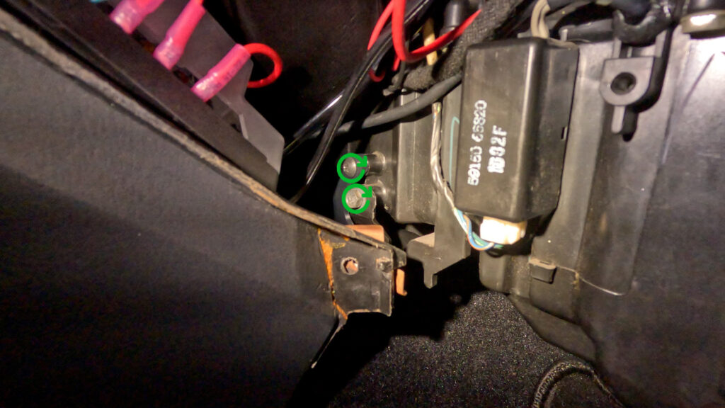
3. Remove Blower Resistor
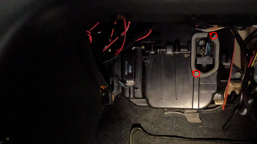
- Remove the Blower Motor Resistor by first unplugging it, then remove the two screws. Don’t loose these.
4. Remove Sil Plate
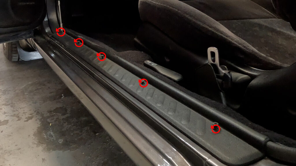
- Unscrew the plastic clips, til the screw comes out a bit. Then you can just gently lift the sil plate up, an dit should come right out.
5. Remove Kick Panel
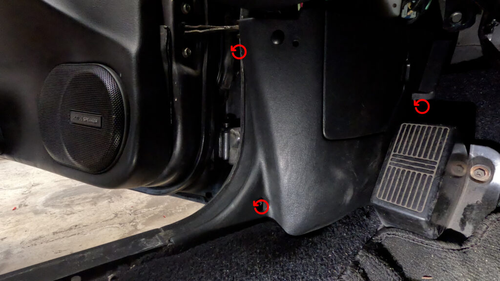
- Remove the screw in the lower left section. In the door jam, there may be a plastic clip. And then behind the dead pedal there is another bolt/screw. Remove all Three, and pull the kick panel straight back.
6. Remove Under Dash Panel
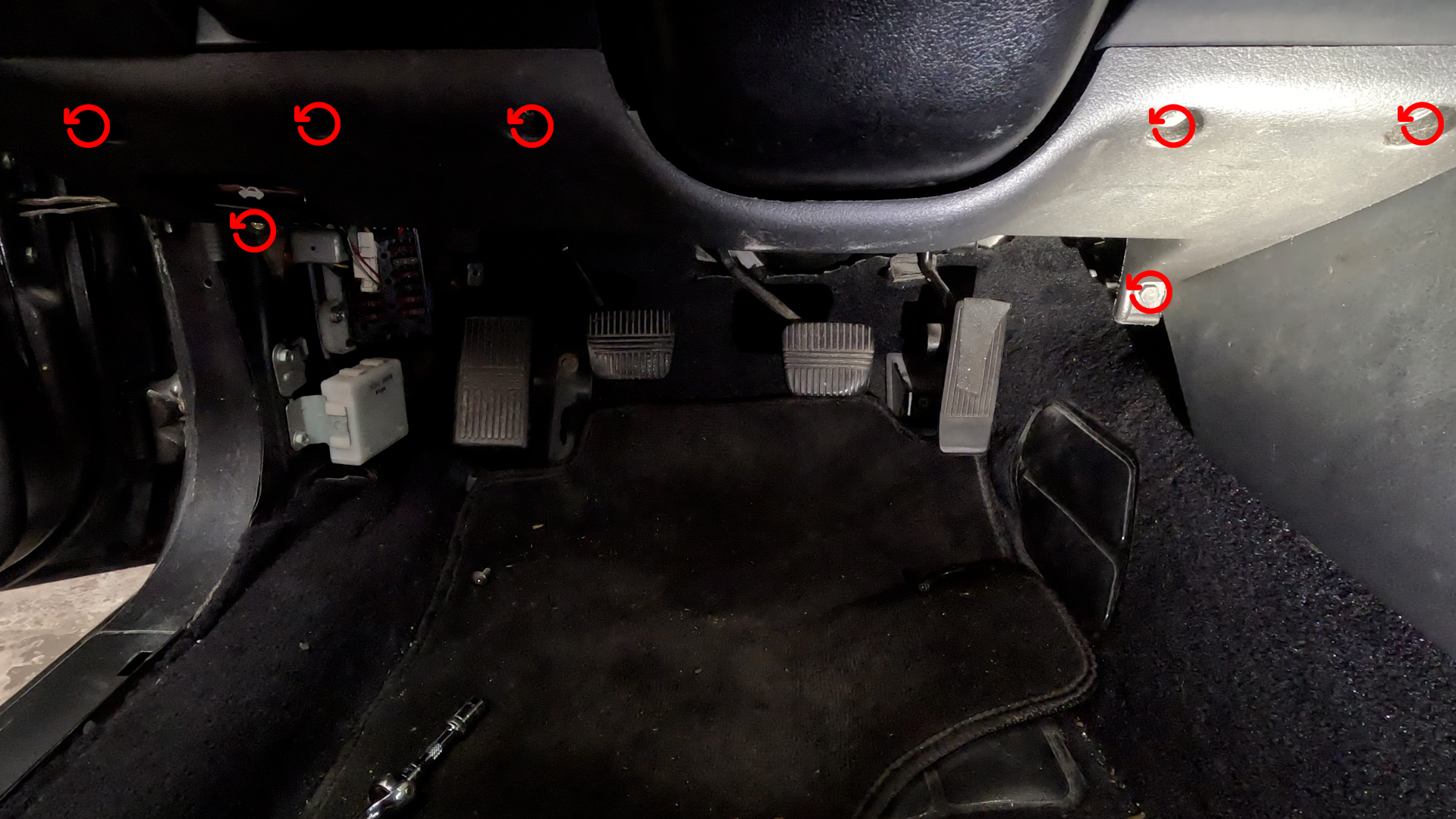
- Remove the 7 10mm bolts as shown in the picture. This will lower the Panel. Once its free, you need to unplug the Floor Light, and unbolt two more 10mm bolts holding in the Hood Release Handle. You have to go in from underneath to get them. You could technically do this first
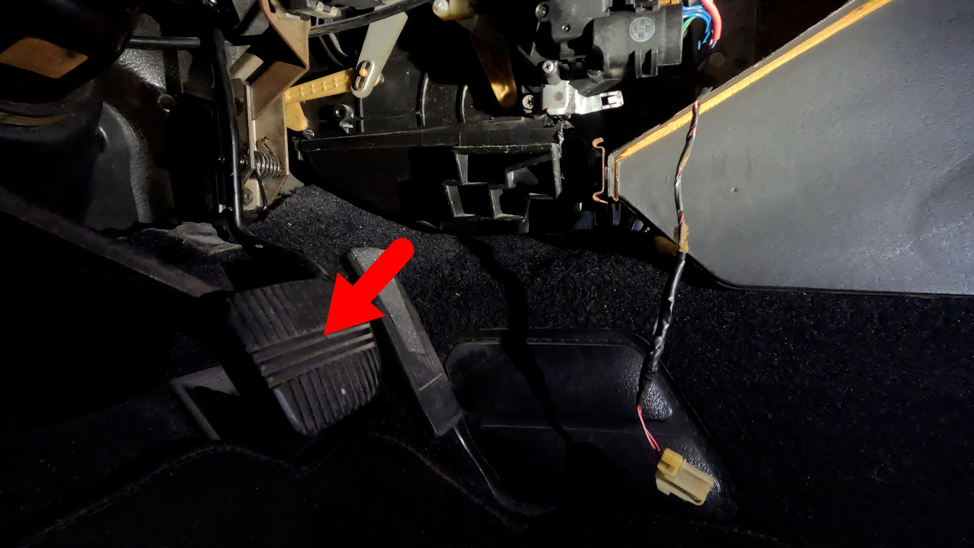
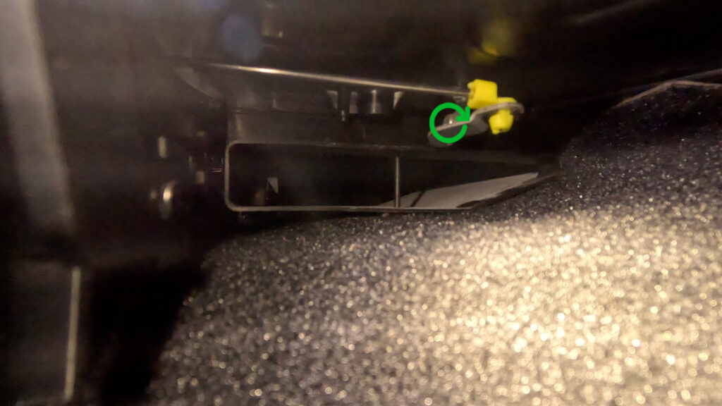
7. Remove Floor Vent
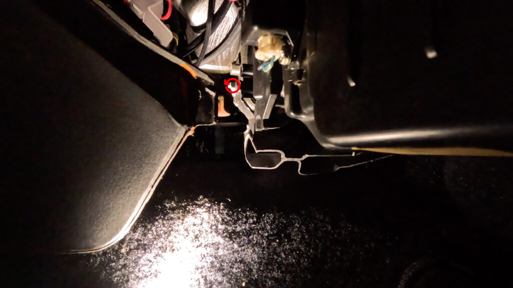
- Remove the Floor Vent. So go in to the Passenger floor side, and looking under the dash, you’ll see the floor vent. Remove this screw by using a Wrench, or a very small ratchet, or screwdriver. Once the screw is free. You can just grab the vent and pull outwards. and it should pop free.
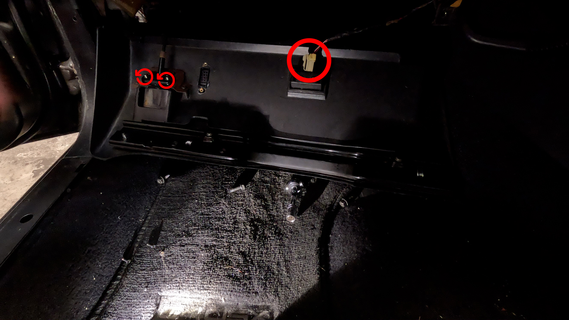
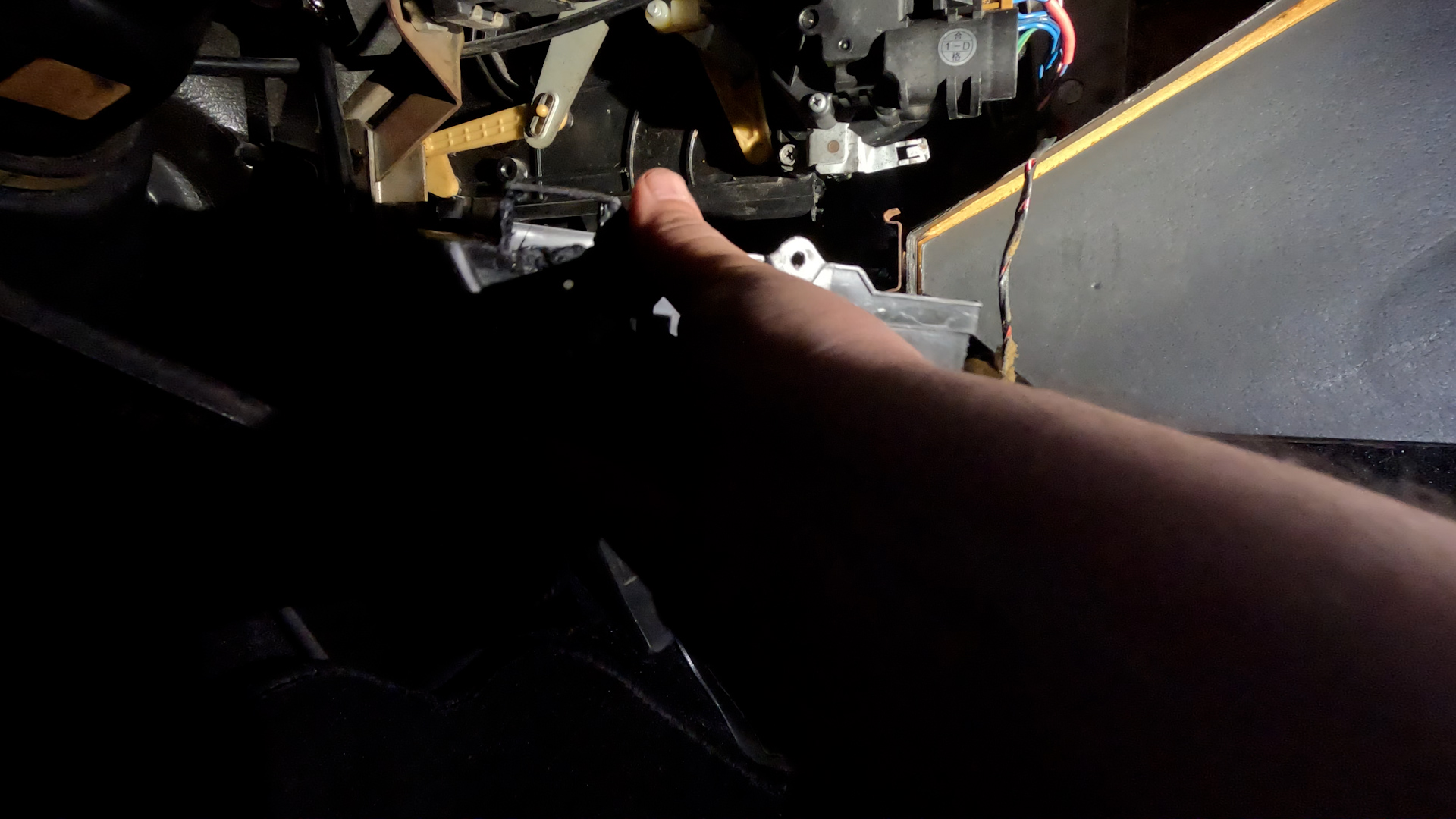
8. Remove Door Mode Bracket and Wire
- Here you’ll see the Bracket connected to a cable running up to the Manual Climate Control Unit By a 10mm Bolt. Then at the end of the wire is another bracket held in by a Phillips screw. You’ll have to contort a bit, but you can come in from the front where the radio was, and get a screwdriver all the way back there. Once the bolt and screw are removed, the whole assembly should come out.
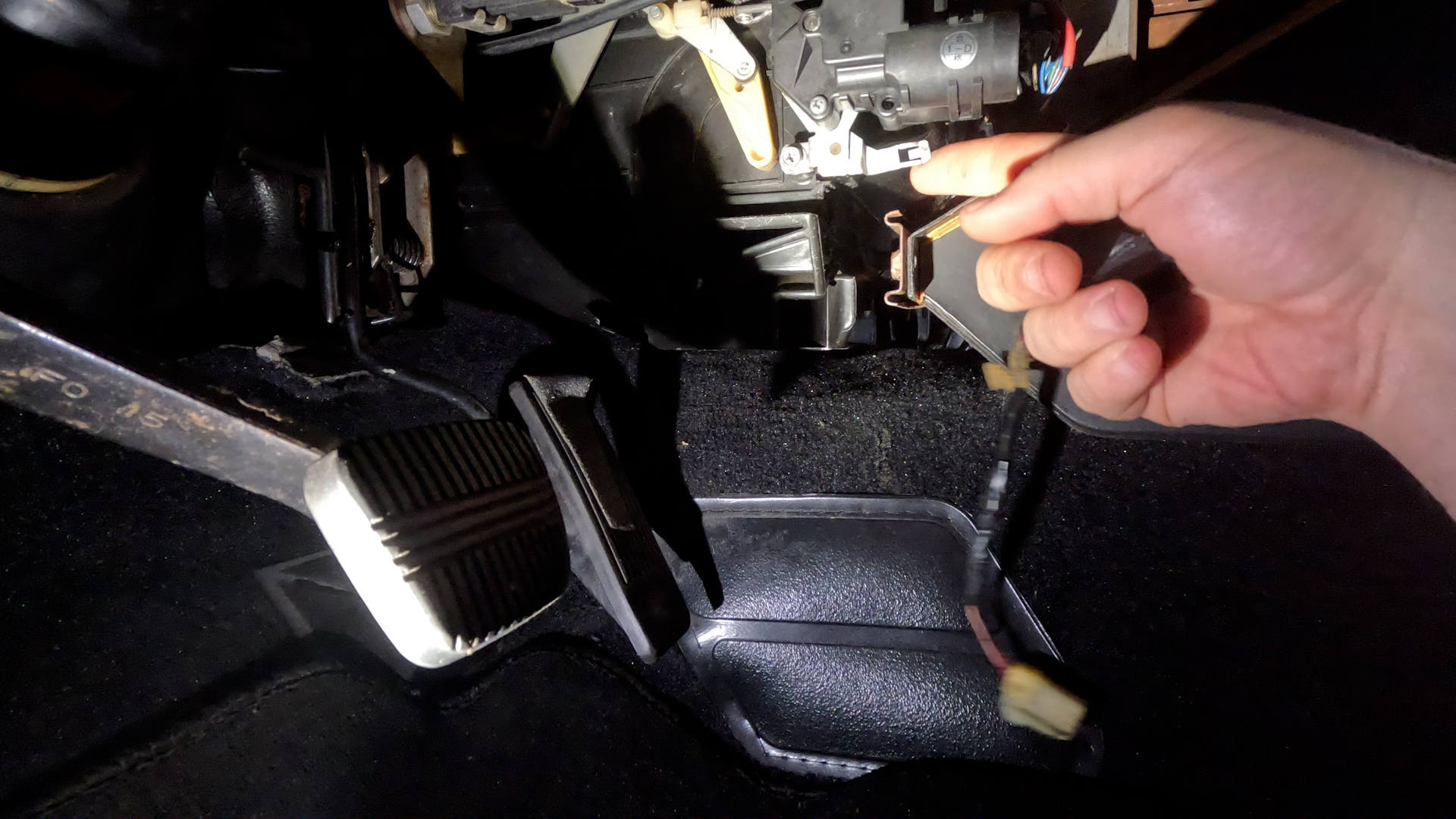
9. Remove Manual Climate Control Unit
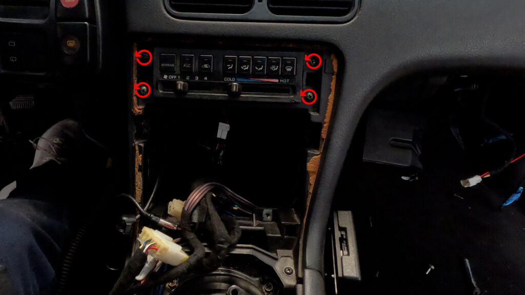
- Remove the Climate Control Unit’s 4 Phillips head screws. Push the unit in, and then down, and pull out through the opening where the Radio was. Then unplug the two connectors. The 6-pin, and the 16-pin, and pull the climate control out. The push wire is long, and catches on wires. so don’t yank it out.
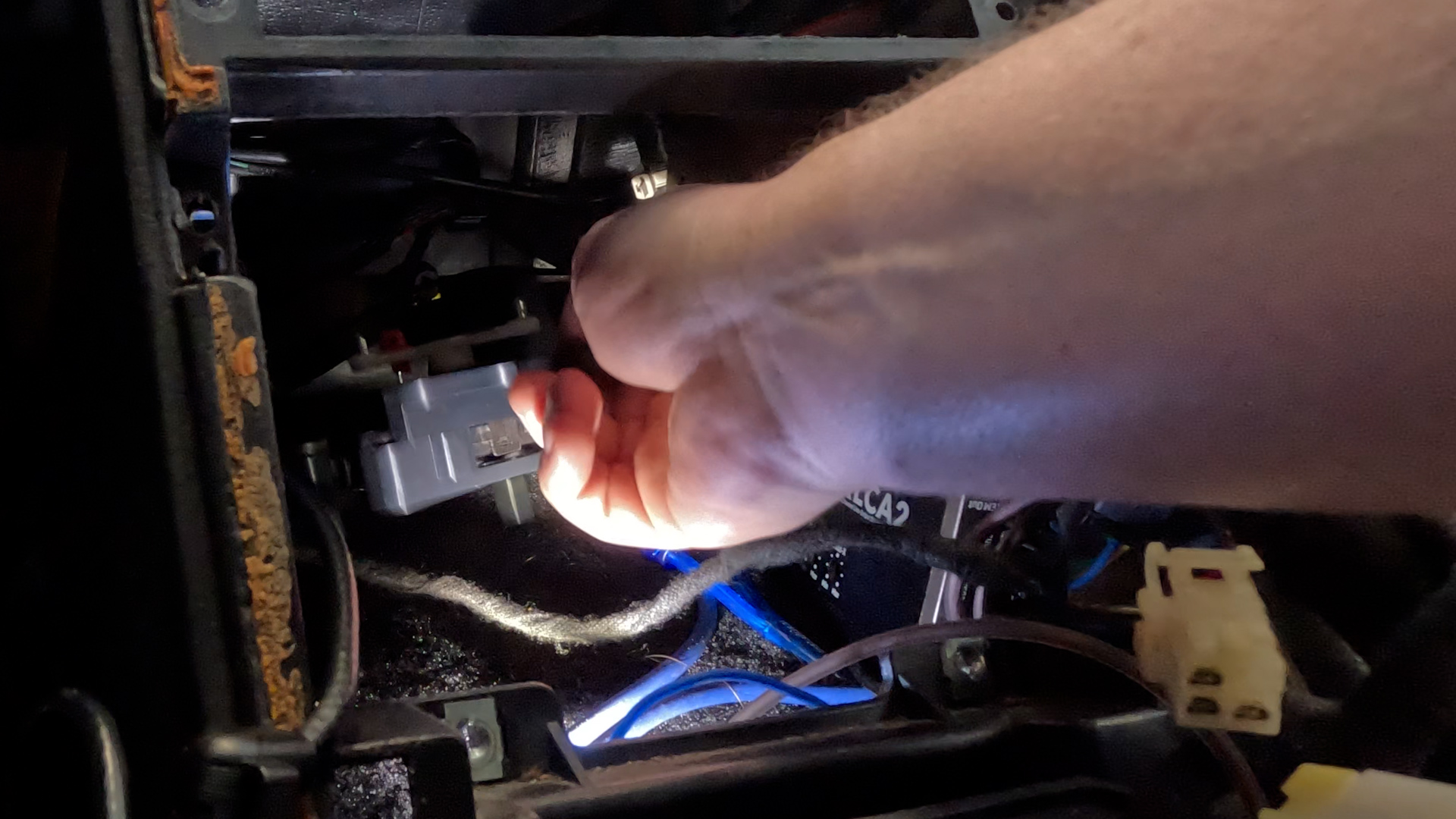
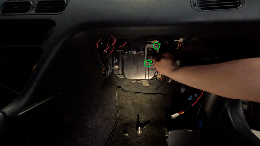
10. Remove Lower HVAC Box.
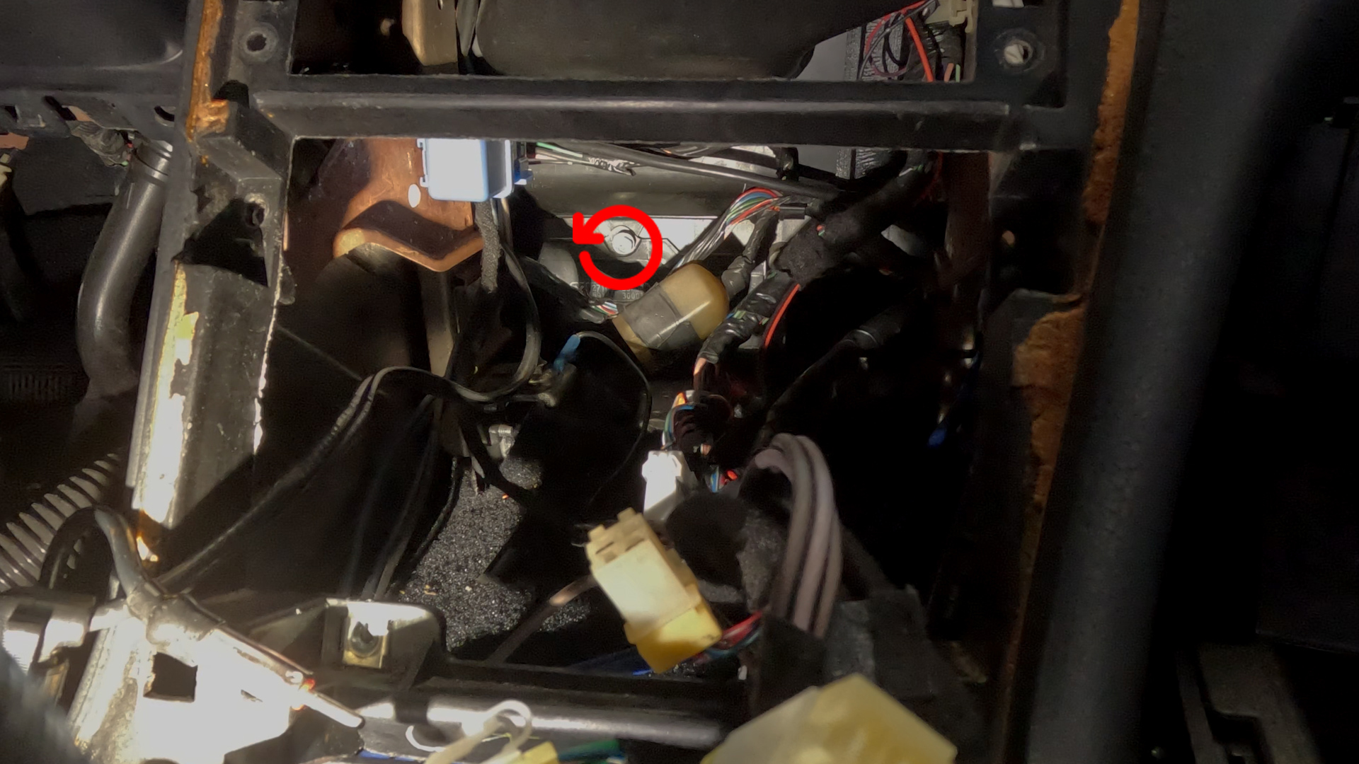
- There is one screw on the top center of the lower box. Look through the Cavity all the way to the back, you should see a single screw. Unscrew that, and pull the lower portion down, and it should pop free. Then go to the Drivers Side foot well, and pull down one last time, then slide the box out through the opening. It is a tight fit, so you may have to squeeze it a bit to get it out.
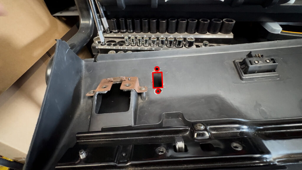
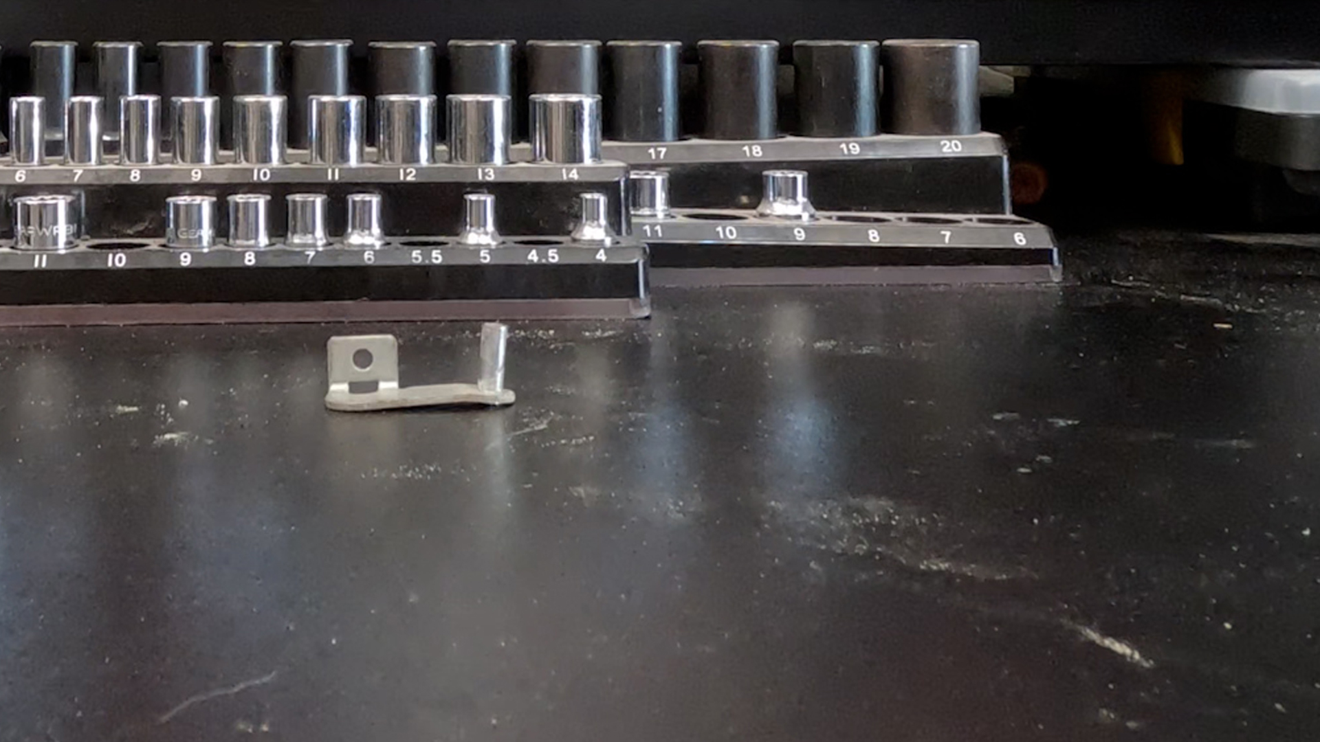
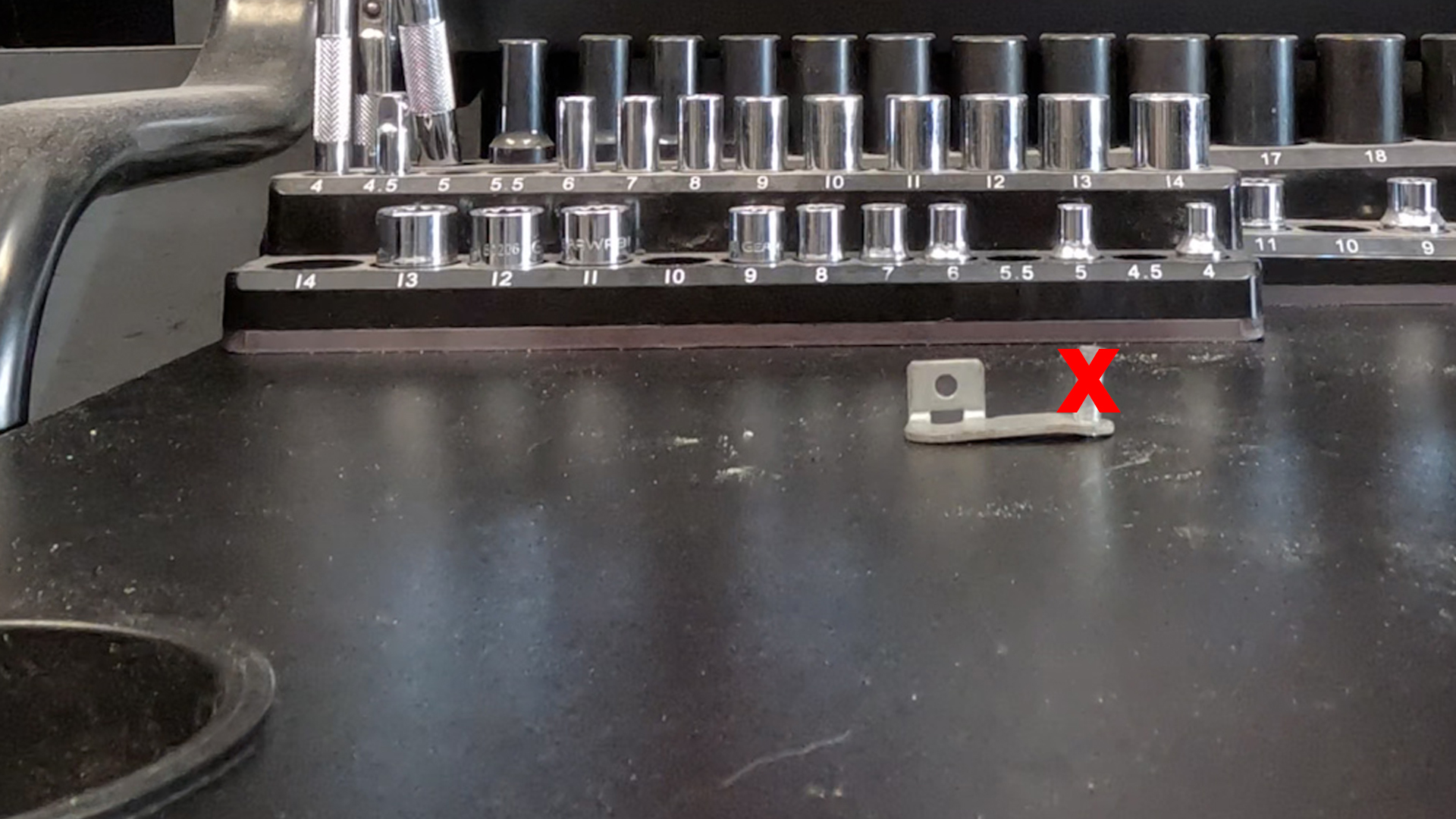
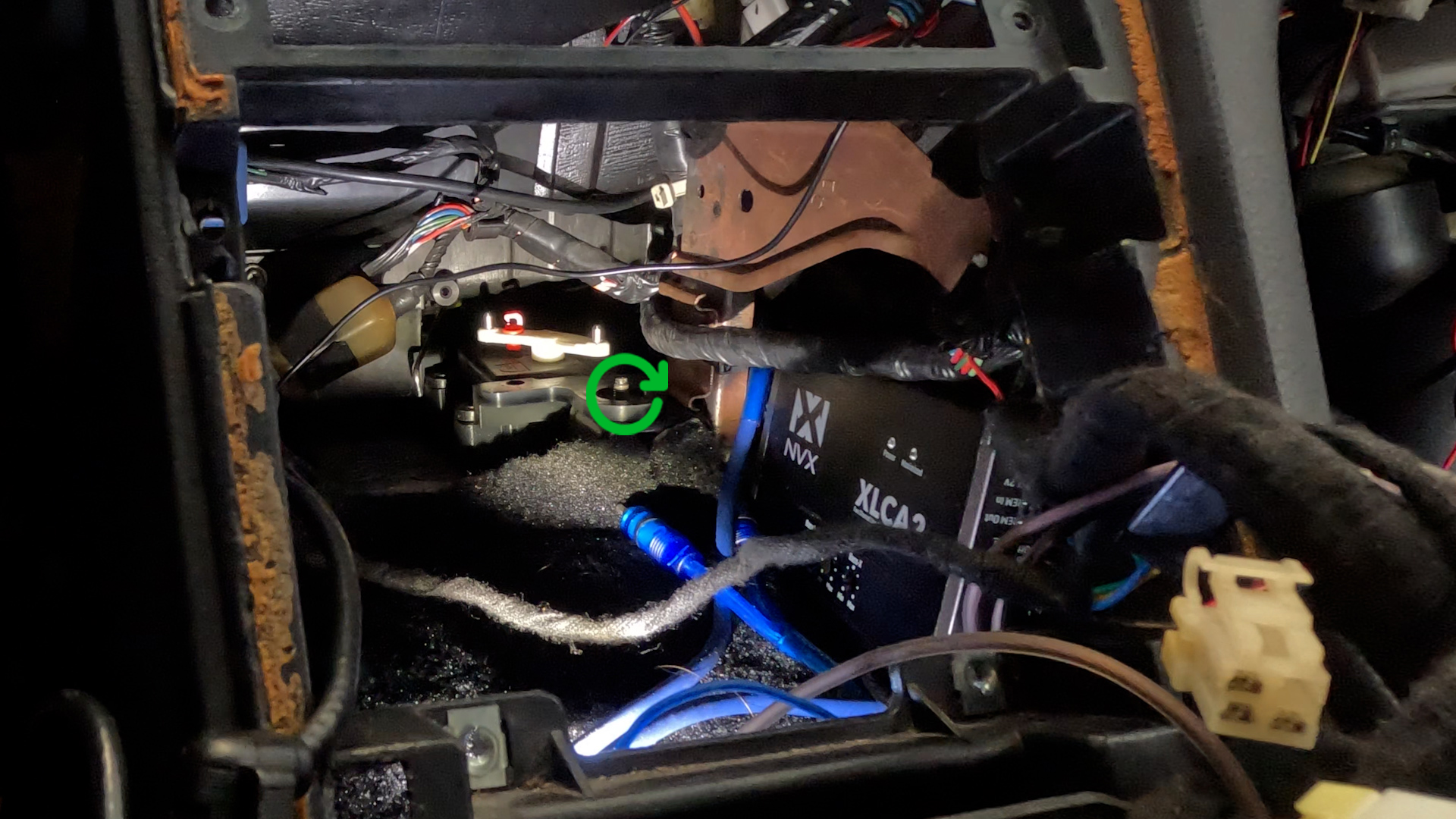
11. Remove Metal Brackets
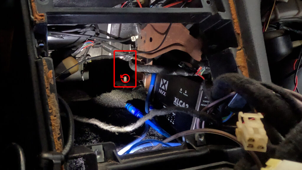
- Remove the two Metal Brackets in the back of the Cavity. They’re held in by one 10mm Flange Nut on each side. Make sure you keep thse nuts. I’ve already removed mine. Hence the Red Rectangle, showing where the right one would be. There is one to the left as well. Ignore the Box and wires. Thats not important. Nothing to see there.
4. PREPARATION
1. HVAC Box and Aspirator Preparation
1. Cut Hole in Lower HVAC Box
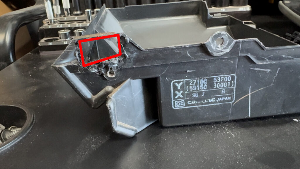
- I already cut mine out before I thought to make this tutorial. So…Deal with it. But basically, there is an indent in the plastic that you should cut along. And then take the Aspirator, and make sure it fits. But don’t install it. There is also a hole for a screw, that you can add by just screwing through the plastic to secure the Aspirator.
2. Aspirator Hose
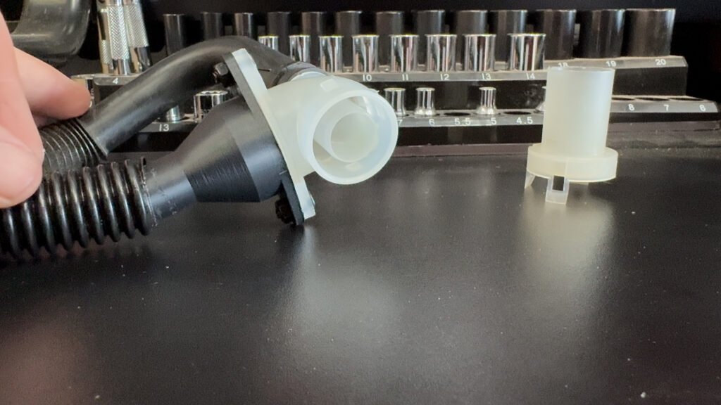
- Okay, SO, apparently you don’t absolutely need this part. But I’m a completionist. What this does, is takes the air that is going to blow OUT of the HVAC box we just cut, and turn it into suction. It does this by pushing air out, and past the open end of the tube face that you see in the picture. This then draws air out from the tube in the back, creating suction. The other end of this is connected to the interior Cabin Temp Sensor. Which draws air from the cabin across the sensor to get an accurate reading, to feed into the DCC.
- I haven’t 3D modeled the actual aspirator part yet. But you can get one off a mid 90’s Maxima, or I30.
- Note: The JDM version has this function built into the aspirator that connects to the HVAC. However, its a very tight fit there with everything. So I decided to do it this way to move things to where there is more room.
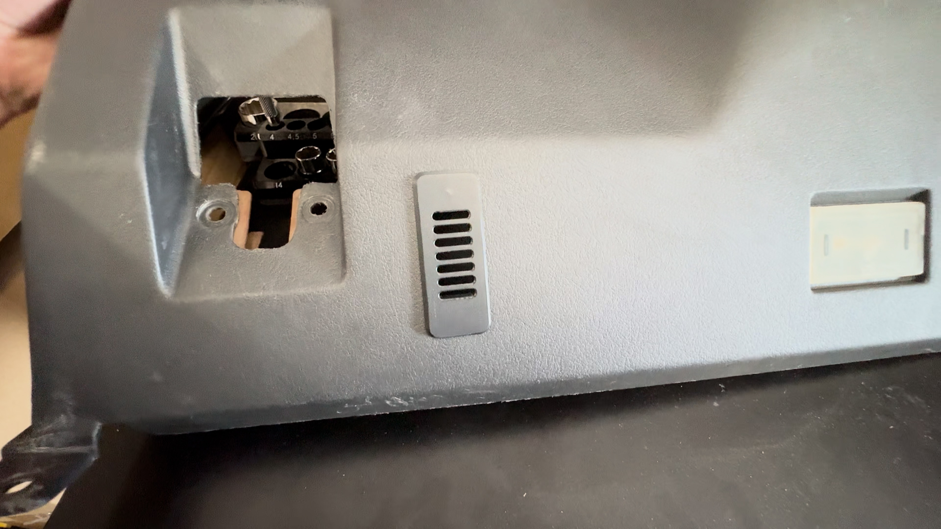
3. Cut Hole in Lower Driver Panel
- Cut a rectangle, and two holes to fit the grill, and mounting point of the Cabin Air Temp Sensor. The 3D Print file should have a template included. And you can place this wherever really. I chose to place it here.
4. Insert Grill and Mount Bracket
- Insert the 3D Printed Grill into the bottom. And on the opposite side, mount the Bracket. I used Thread Inserts into the grill, and put 4mm Screws in to keep it in place. The Inside Cabin Temp Sensor mounts here.
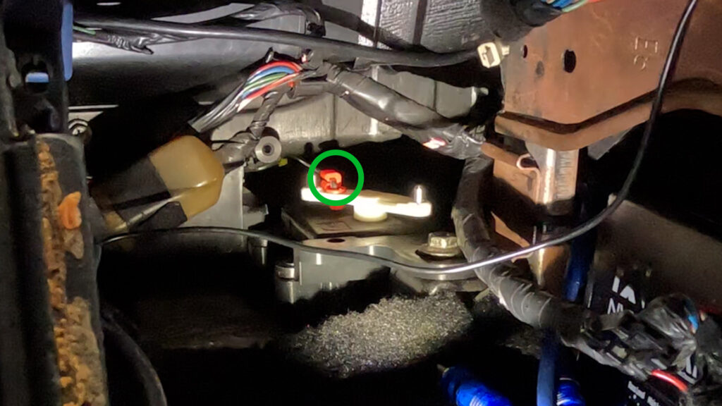
2. Blend Door Motor Preparation
1. Drill Hole into the arm
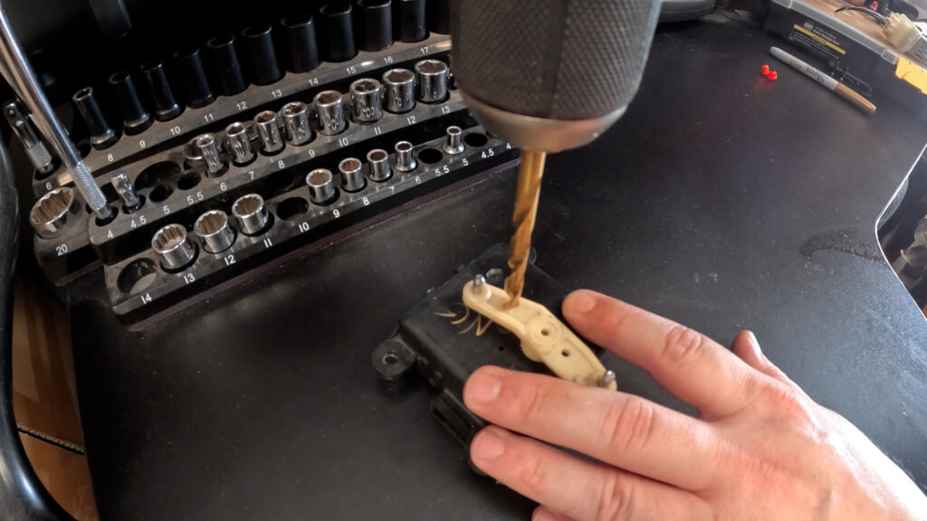
- So, you want to drill a hole in the arm using a 15/64″ Size Drill bit. And you want to go about 6.5mm from the plastic indent at the end of the arm. Be careful to not drill into the housing.
2. Shave the ridges of the arm
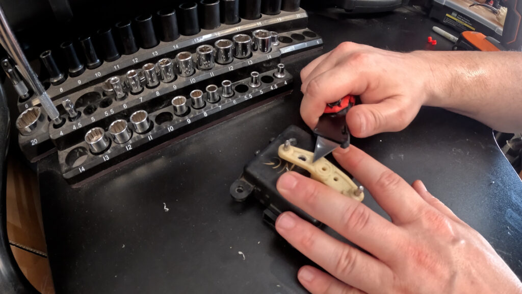
- Now you’ll want to shave the ridges on the arm. On either side of the hole you drilled. This will allow the red Rod Clip to sit flush, and spin freely.
3. Install Motor into Bracket
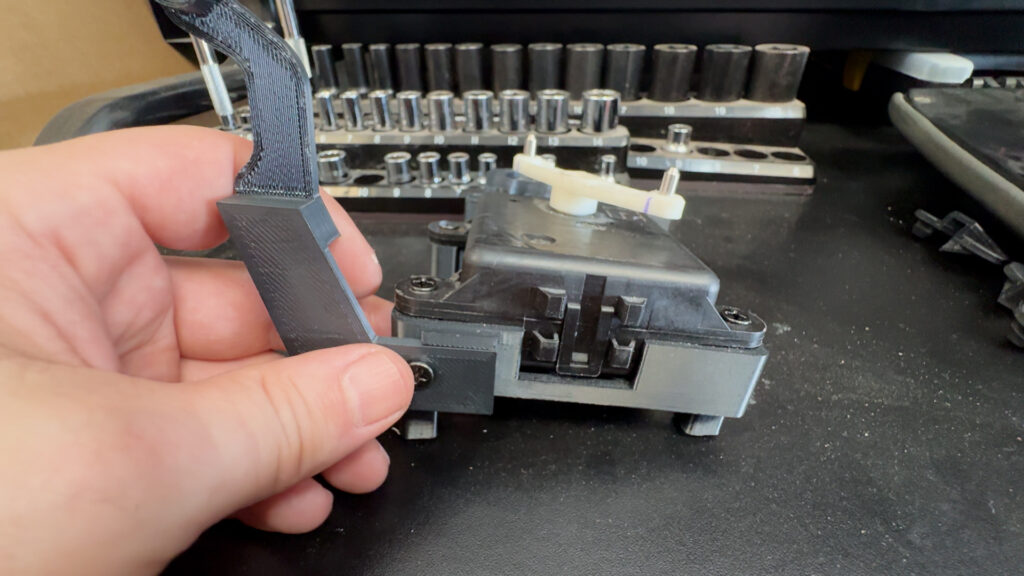
- Next you’ll want to install the motor into the 3D printed Bracket. It is held in place by four screws that go into Threaded Inserts in the mount, if you decided to go that path.
- You want to make sure the Plug connector is Facing to the right, in relation to the View of this picture.
4. Make the Rod arm
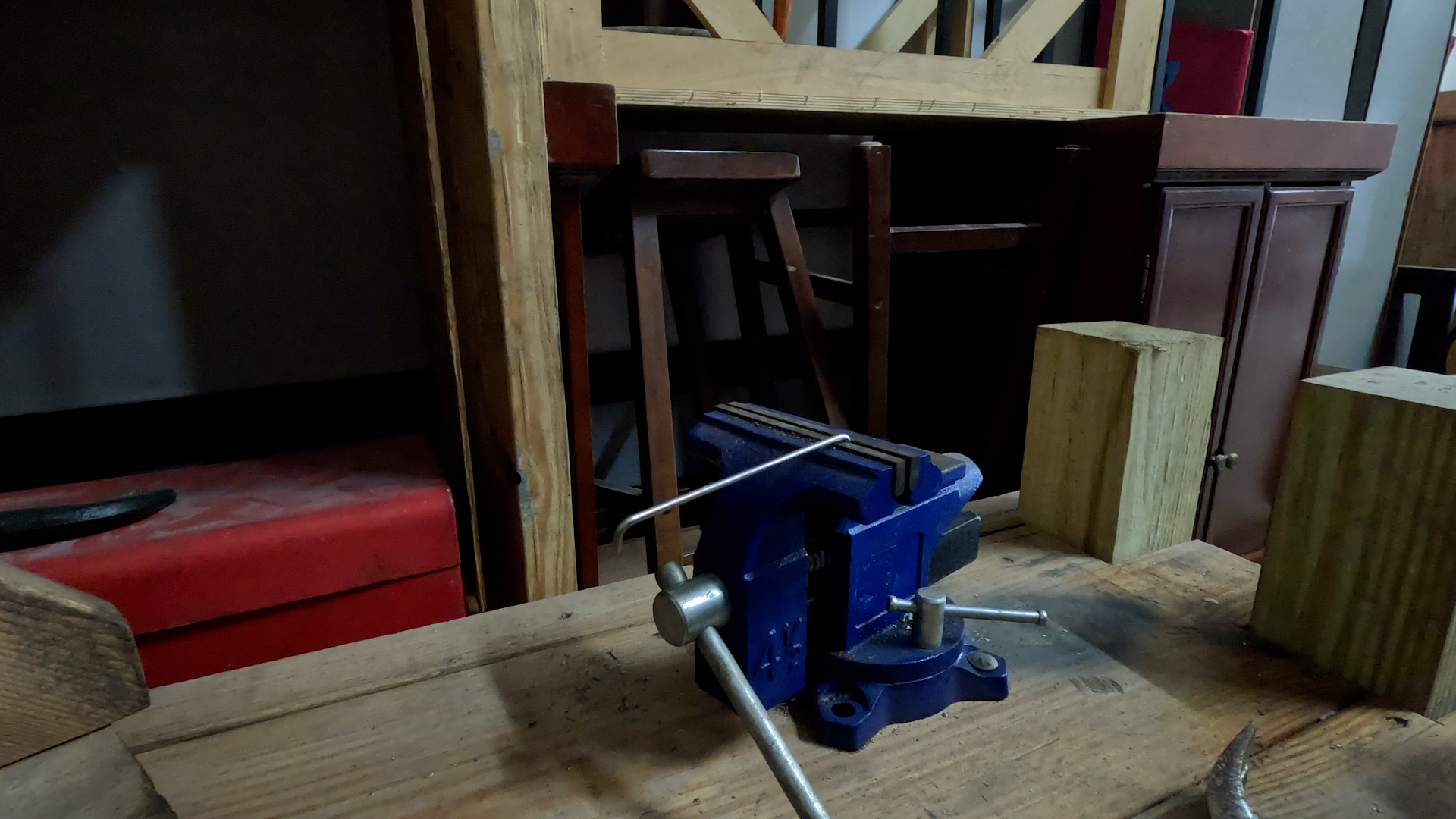
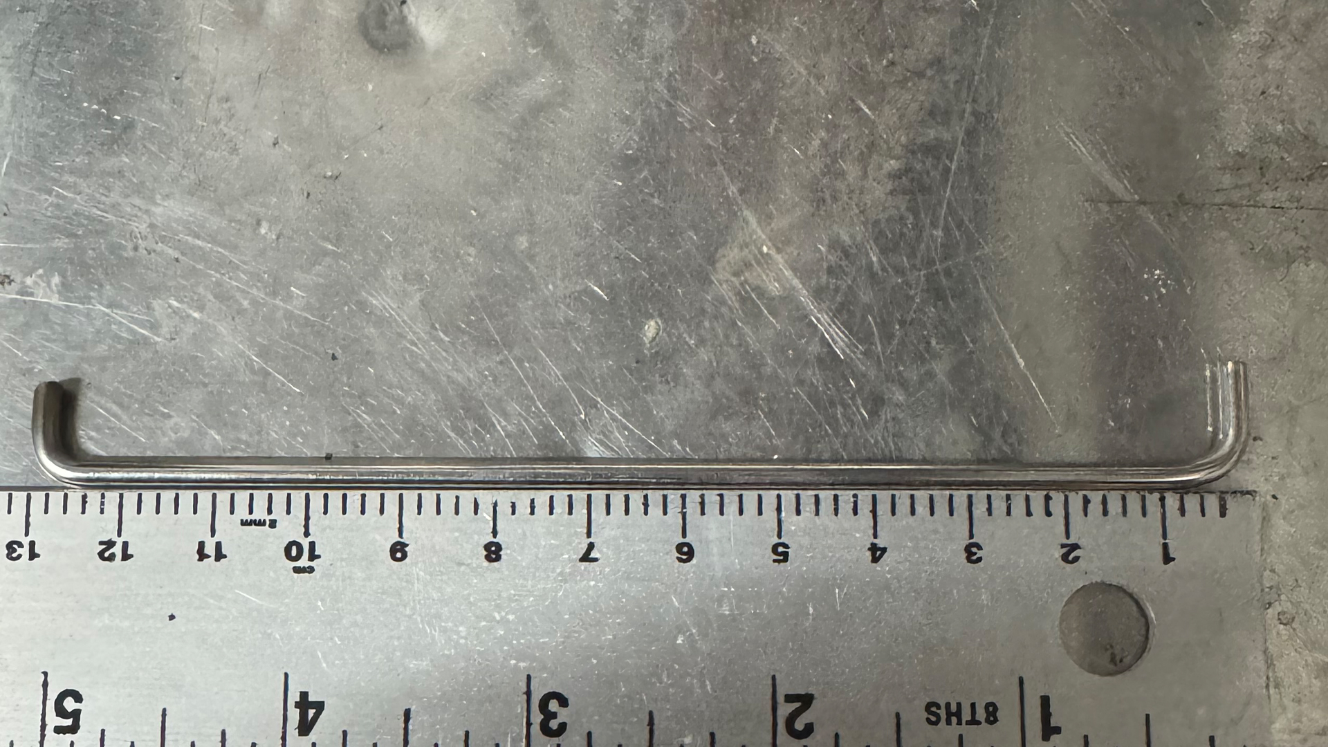
- Grab your Rod arm (3mmx300mm) And put half an inch into a vice. Then use a hammer to bend it to a 90 Degree angle. The length, from bend to bend should be 13cm. Bend the other side in the same direction, and cut off the excess. You want to make sure that when this is inserted into the Arm, the rod doesn’t touch the main body of the motor.
- Do not insert the rod yet.
5. Make/Purchase the Bracket for the Door
- You have two options here. You can modify your bracket, by cutting off the metal rod at the end. And drilling a hole with the 15/64″ drill bit. However I have not tested this, so the arm length may have to change possibly. Otherwise Just purchase the bracket listed above in the materials section, and skip this step.
3. Sunload Sensor Grill
1. Drill Hole into the Defrost Vent
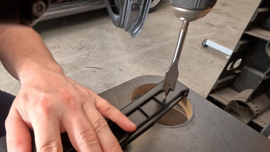
- This is the Right Side, or Passenger Side vent. Be careful…your vent is likely to just explode when you remove it. So…just be mindful.
- So, you want to drill a hole in the vent near the edge. Notice the location in the image, I’m drilling from the underside. The Spade bit is 5/8″, but is juuuust too small. So once you make the hole, angle the bit to widen it as neccesary to fit the Sunload Sensor. Just refer to the size of the sensor, and be cautious not to make the hole too big.
2. Insert the Sunload Sensor into the Grill
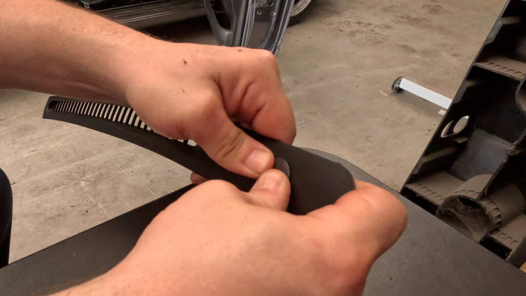
- Just press the sunload sensor through the hole you made, and it should kind of pop into place.
5. INSTALLATION
1. Reinstall the HVAC Box
- Install Lower HVAC, goes in the same way you took it out.
- Its been a while since I originally did this. There is a little metal tab that is part of the Door Mode Actuator. You may need to bend it out of the way slightly to get the Aspirator in.
- Screw in the HVAC box in the cetner through the console.
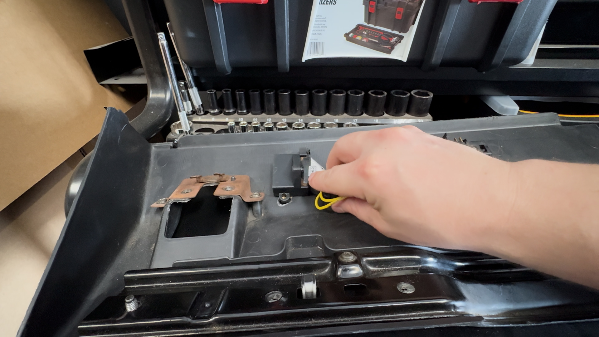
2. Install Blend Motor and Bracket
- Weasle the Bracket Assembly for the Blend Door Motor all the way back. It will go past the bracket, and the Stud on the right side fits through the whole on the back of the bracket.
- Then Use the Flange Nut you removed earlier to secure the bracket into place.
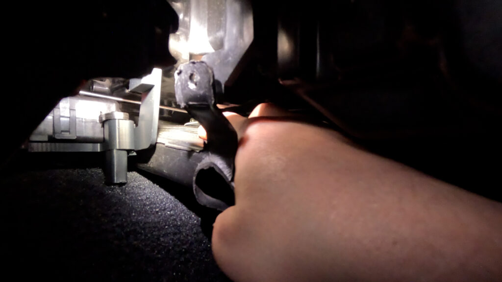
3. Install Blend Door Bracket
- View is from Passenger Footwell. Take the Blend Door Bracket, and screw it into the metal rod that rotates the blend door with the same Philips screw that held in the original. It should look like it does in the picture. Once that is secured. You’ll place your clip into the hole, ensuring it fits snugly and pops in. Then take your Rod, and insert it down into the hole, and rotate the clip to lock it in place.
- Make sure the rod is inserted between the HVAC box, and the arm of the bracket. So it can reach the arm easily.
4. Reinstall Passenger Foot Vent
- Its a bit tricky, but you have to push the vent down against the carpet, and push it in. It should pop into place, and the screw hole should align with the box where it was originally. If its not aligned, its not in properly.
5. Screw in Bracket and Vent
- Screw in the Foot Vent with the screw that was originally there. Then use the extra Screw from the materials list, to screw the arm of the bracket just above where the Foot vent screws in.
6. Install Rod to Arm of Motor
- Now you can slide the other end of the rod into the hole of the clip. Then rotate the clip to snap onto the rod. Now your Blend Door Motor is installed.
7. Install Q45 Blower Motor Resistor
- Install the Q45 Blower Motor Resistor with the Two screws that go into the plastic box. Then plug in the USDM harness. You don’t need to do anything else here!
8. Install the Harness
- If you followed the Wiring Diagram Provided, this will be a bit easier. As you can take the Accessory Connector for the Sensors and put that in first.
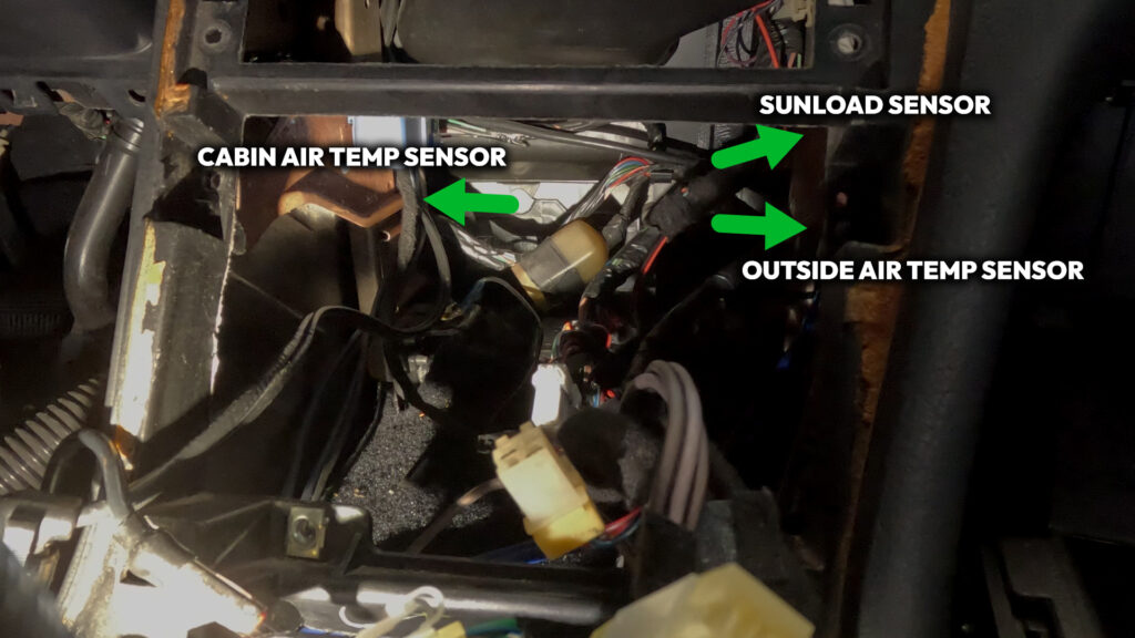
- The Cabin Air Temp Sensor wire needs to go to the left towards under the Steering wheel.
- The Sunload Sensor goes to the right, in an upward position towards the Defrost Vent.
- The Outside Air Temp sensor goes to the Right, and heads towards the Gromet for the Main Harness that goes through the firewall.
9. Install Harness continued
- Remove the Climate Control Unit’s 4 Phillips head screws. Push the unit in, and then down, and pull out through the opening where the Radio was. Then unplug the two connectors. The 6-pin, and the 16-pin, and pull the climate control out. The push wire is long, and catches on wires. so don’t yank it out.
10. Remove Lower HVAC Box.
- There is one screw on the top center of the lower box. Look through the Cavity all the way to the back, you should see a single screw. Unscrew that, and pull the lower portion down, and it should pop free. Then go to the Drivers Side foot well, and pull down one last time, then slide the box out through the opening. It is a tight fit, so you may have to squeeze it a bit to get it out.
Now it is time to install everything! Its not too bad in terms of difficulty, its just kind of time consuming. I’d suggest not reassembling things right away, as you’ll want to test and make sure everything is working correctly before you put everything back together.
- So, the hardest part first. You’ll need to run the 11 feet of wire from the front of the car, through the engine bay to the ECU hole in the firewall. Through the car up behind the glovebox, and around into the center console cavity. Its annoying but it must be done.
- Once the Outside Ambient Temp Wires have been ran. You’ll need to find a place to secure the sensor. You can find a bracket specifically for these online, or at a junkyard. Or fabricate something of your own. It just needs to be out of the way, in front of the engine bay and radiator support, and behind the Bumper. You may want to de-pin the connector from the wires to make it easier to snake into the grommet in the firewall.
- Run the Sunload Sensor up from the Center Console Cavity to the right, behind the glove box. Its a bit tight, but not too difficult to fish the wire up to the open vent where the Defroster Vent was when you took it out. Make sure you have a decent amount of slack on both sides. Ziptie in place if you desire.
- Remove Blower Motor Resistor located behind where the glove box would be. Do this by unplugging the connector and removing its two screws. Replace with the unit from the Q45. It should bolt in place. Then plug back in the connector. No need to cut anything here!
- Reinstall lower HVAC box assembly, that now has a hole cut in it, and screw into place.
- Get your contortionist hands ready. Install the Aspirator. You can either glue it in place, or use rubber beutal to seal it in place. Then, very very painfully try to screw it into place. The hose adapter of the aspirator points up along the line of where the dash panel goes.
- Cut about 6 inches of Hose, and connect one end to the Aspirator. Then the other end goes to the adapter piece, that will go to the vortex generator.
- Attach Rest of hose to The vortex Generator, and run this to the Inside Cabin Air Temp Sensor. Just let it sit there for now.
- Bolt bracket (27156-51E00) to blend door with Philips screw.
- Install rod clip to bracket. Then insert cut and bent rod into the hole, and rotate the clip to snap it onto the rod.
- Install Maxima Blend door motor that is attached to the 3D bracket with. This goes on the Stud and is secured by replacing the 10mm Flange nut that was removed earlier
- Clip Goes into the Blend Door Motor Arm first. Then place Rod into the hole, and rotate clip to snap onto the rod.
- Plug your newly made DCC harness to USDM harness 16-pin and 6-pin that originally went the back of the Climate Control Unit.
- Plug in the Accessory Connector that goes from the harness to the Sunload Sensor and Outside Ambient Temp sensor.
- Plug in the Blend Door Motor connector to the mounted Motor.
- Run the wire for the Inside Cabin Air Temp Sensor out to the left, by the Aspirator Hose, and connect it. Leave unmounted for now.
- Connect Ground wire to Stud on the left side of the Cavity, where the bracket was removed.
- Make sure wires are connected to the Sunload Sensor, Outside Ambient Temp Sensor, Cabin Air temp Sensor, and Blend door Motor. Just do a quick double check.
- Plug in the Connectors to the Back of the Digital Climate Control Unit.
- Now its time to test everything before putting it all back together.
6. TESTING
Great! Everything is installed! But now we need to make sure we didn’t mess anything up along the way. Thankfully Nissan built in a self-diagnostic test you can run. Below details exactly how to do that!
- Turn the Key to Accessory On position. Within 10 seconds of turning the key, press and hold ‘OFF’ button on the Faceplate for 5-10 seconds until all segments on the display light up.
- Test 1 – Display Test. This just lights everything up so you can see if you have any bulbs burnt out. If you do, refer to the last section of this guide!
- Press the red UP arrow to get to Test 2.
- Test 2 – Sensor Check. Checks the Input signals from each sensor. Its 90’s tech so its a little slow, give it a second.
- 20=all ok
- 21=ambient
- 22=in-vehicle,
- 24=intake,
- 25=sunload (test in sunlight to prevent error, or Hold a decent flashlight up to the top of the sensor. It should clear. to prevent this error)
- 26=PBR.
- Press the red UP arrow to get to Test 3 or Blue Down Arrow to go back to Test 1.
- Test 3 – Door Mode Motor Checks. This test takes a little bit.
- 30 = all modes ok
- 31 = vent, 32=B/L
- 33 = B/L
- 34 = Foot/Def 1
- 35 = Foot/Def 2
- 36 = Def
- Press the red UP arrow to get to Test 4 or Blue Down Arrow to go back to Test 3.
- Test 4 – Actuators Test Pattern. Press the defrost button to cycle through modes. (Something to note here. When it gets to DEF, it makes a really horrible noise up in the right side of the Dashboard. Something is Grinding. Quickly change test when you hear this. I am not smart enough to know why it does this, but it hasn’t effected how anything actually works. So….. I ignore it!)
- 41 = Recirculation / Full Cold / Vent
- 42 = Recirculation / Full Cold / Vent
- 43 = Recirculation / Full Cold / Vent & Foot
- 44 = 20%free / Full Hot / Vent & Foot (this shouldn’t be wired up?)
- 45 = Outside Air / Full Hot / Foot
- 46 = Outside Air / Full Hot / Defroster & Foot
- 47 = Outside Air / Full Hot / Defrost
- Press the red UP arrow to get to Test 5 or Blue Down Arrow to go back to Test 4.
- Test 5 – Temperature Readings. Press defrost button to toggle through sensors (ambient, in-vehicle, intake; in that order).
- If the temp reads -22, then that sensor is not working. The temperature can also be adjusted to compensate for differences between temp setting and the temp felt by driver. It can be adjusted 6 degrees up or down. To do this while in Test 5, press the fan switch and then the temp adjustment can be made using the Up/Down arrows.
- Hit the Auto button or turn car off to exit self-diagnostic.
- Troubleshooting
- Problem: No movement of Hot / Cold Mix Door when raising and lowering temp settings on the control unit.
- Check: Make sure the In-Cabin Air Temp sensor is plugged in. If this sensor is not plugged in, only diagnostic mode will cause actuator movement.
- Problem: Fan runs on full no matter what settings selected.
- Check: The Q45 Resistor may be touching and grounding out against a copper A/C metal line inside the cold air box. Remove the resistor, look inside air box and gently bend the line in a bit OR grind down the fins so it does not touch.
7. Reassemble
You’ve troubled your shoot! And everything is working fine! Hell yeah Brother! Now its time to reinstall everything and get the car looking back to stock-ish, so you can Flex your JDM DCC out on all your friends.
- Replace Passenger Foot Vent by pushing it back into place, it should kind of snap in. Then mount it with the screw.
- Reinstall Glove box. Line up the two locator pins with the bracket on the bottom, And close the Glovebox til it clicks into place. Then remount with the two screws underneath.
- In the Lower Dashboard Cover, mount the vent into the holes you cut earlier. Then put the Inside Cabin Air Temp Sensor Bracket, connected to the sensor, to the Vent from the back side. Screw into place.
- Remount the Hood Release handle with the two 10mm Bolts.
- Plug in the Footwell light, which is the 2-pin connector.
- Press the lower Dashboard Cover into place, and mount with the 7 10mm Bolts. 5 of them should be longer and go along the underside to the Cluster Bezel, and two shorter ones should go at the bottom of the panel.
- Install Drivers Side Kick panel. 1 Phillips screw at the bottom. And a 10 mm Bolt at the back by the dead pedal. And a clip for the Door sill Side.
- Install Plastic Kick Plate by lining up the holes, and pushing the clips down into place.
- Push DCC in through radio hole, and place the DCC behind, and mount with four screws.
- Install Radio by reconnecting connector and Radio Antenna. Then make sure the wires are tucked away neatly, and place radio in, and mount with the four screws.
- Install shifter bezel by pushing the clips back into place. Hopefully you didn’t destroy them in the removal process.
- Install shift knob by rotating clockwise.
8. Lights.
This stuff is old. And chances are the light bulbs in the DCC you purchased are old, and burnt out. So you’ll want to replace them, and depending on how neurotic you are, there are many many ways to solve this issue. But mostly, you’ll want to look for T3 Neo Wedge lights. They have an 8mm Base. There are four of these lights. 1 for the left side, 1 for arrow buttons, and two for the right side. They just unscrew with a flathead, and you have to kind of pull them out with tweezers, and then put the new ones in and screw them.
1. You can purchase brand new LED lights that just replace the existing ones. And it works just fine. But they are quite bright, however you can get them in whatever color you want, which is pretty neat. I found WLHJ 10x White T3 Neo Wedge 3030’s on Amazon that worked just fine. Be mindful of Polarity with LED’s. So you may have to take them out, and turn them 180 degrees.
2. You want to keep it looking factory. You can purchase Warm White Halogen bulbs. They make things very orange, so the solution is to take the blue rubber condoms that should be on the lights that you take out of the DCC, and peel them off, and place them over these. HOWEVER. Something I’ve noticed is that the ‘white’ created by these condoms, is different than most of the factory ‘white’ in say the stock radio unit. Which can be distracting. The solution for this, is to go to a junkyard, and find USDM Nissans from the 90’s. And steal the blue condoms off those, and use them instead. That creates the correct white balance with a factory Radio head unit. I know this, because I’m insane, and was bothered by it, and kind of stumbled on to it by mistake.
8. Considerations.
So, a couple of things. I could not have done any of this without the help of those who have come before me. I want to give a special shout out to NismoLK and KoukiMonster on NicoClub who really helped me find my way through. So at the end of the day I’m maybe contributing like 10% new information.